Brand:
MITSUBISHI
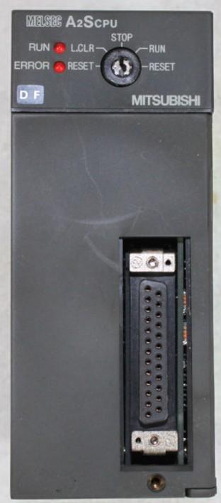
A2SCPU CPU unit
MITSUBISHI A2SCPU Manual And Instructions
A2SCPU datasheetPDF datasheet
A2SCPU Common InstructionsProgramming Manual
A2SCPU User's Manual
A2SCPU Dedicated InstructionsProgramming Manual
A2SCPU FundamentalsProgramming Manual
MITSUBISHI A2SCPU Product information and technical parameters:
Brand: MITSUBISHI
Name: CPU unit
Model: A2SCPU
Program memory capacity 14K.
Input and output points to the maximum 512 points.
A scan cycle of PLC must pass through three stages: input sampling, program execution and output refresh.
PLC in the input sampling phase: first of all, in order to scan the sequence of all existing input latches in the input terminal of the state or input data read,
And write it into the corresponding input status register,
Refresh the input, then close the input port, enter the program execution stage.
...More relevant models >>>>
A2SCPU datasheetPDF datasheet
A2SCPU Common InstructionsProgramming Manual
A2SCPU User's Manual
A2SCPU Dedicated InstructionsProgramming Manual
A2SCPU FundamentalsProgramming Manual
MITSUBISHI A2SCPU Product information and technical parameters:
Brand: MITSUBISHI
Name: CPU unit
Model: A2SCPU
Program memory capacity 14K.
Input and output points to the maximum 512 points.
A scan cycle of PLC must pass through three stages: input sampling, program execution and output refresh.
PLC in the input sampling phase: first of all, in order to scan the sequence of all existing input latches in the input terminal of the state or input data read,
And write it into the corresponding input status register,
Refresh the input, then close the input port, enter the program execution stage.
Enter 64 points.
Above DC7V.
Response time: 16ms.
16 pin connector.
Output 64 points.
Response time: 16ms.
32 pin connector dynamic input and output data.
PLC is introduced by the relay control technology after the development of micro processing technology,
Can be easily and reliably used for switching control A2SCPU.
As the analog quantity can be converted into digital quantity, the number of digital quantity is just a number of switching value,
Therefore, after the conversion of analog, PLC can also be reliable for processing control A2SCPU
Because the continuous production process often has the analog quantity, the analog quantity control is sometimes called process control.
Analog quantity is not electricity, and PLC can only handle digital quantity, quantity of electricity A2SCPU.
All to realize the conversion between them to have the sensor, the analog quantity into a number of power.
If this power is not standard, but also through the transmitter,
The non-standard power into a standard electrical signal, such as 1-5V, 4-20mA, 0-10V, etc..
At the same time, there is also an analog input unit (A/D),
Transform these standard electrical signals into digital signals,
The analog output unit (D/A), in order to transform the digital quantity after PLC processing into analog quantity -- standard electric signal A2SCPU.
So the standard telecommunication number, the conversion between the number of operations to use a variety of computing.
This requires the resolution of the analog unit and the standard electrical signal. Write adapter for EPROM 28 pinAxis of control: 1.
A1SD75 series components show the MITSUBISHI in the manufacture and design of CNC, frequency converter,
Integrated technical experience in servo system and PLC.
These components have a wealth of feeatures that are sufficient to meet the highest requirements in the application of positioning control A2SCPU.
A1SD75M, SCC net compatible controller, SSC network is the MITSUBISHI servo system control network.
In this network, the MR-H-13, MR-J-B, and MR-J2 servo amplifiers can be connected to a controller via a network system,
The connection is replaced by a pulse sequence and a voltage signal A2SCPU.
...More relevant models >>>>

