 LK Automation Limited
Brand:
MITSUBISHI
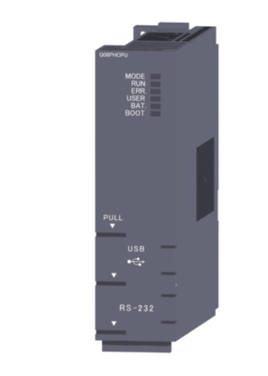
Q06PHCPU Process CPU
MITSUBISHI Q06PHCPU Manual And Instructions
Q06PHCPU datasheetPDF datasheet
Q06PHCPU datasheetPDF datasheet
Q06PHCPU Special InstructionsStrctured Programming Manual
Q06PHCPU Application FunctionsStrctured Programming Manual
Q06PHCPU Common InstructionsStrctured Programming Manual
Q06PHCPU FundamentalsStrctured Programming Manual
Q06PHCPU Multiple CPU SystemUser's Manual
Q06PHCPU Function Explanation, Program FundamentalsUser's Manual
Q06PHCPU Hardware Design, Maintenance and InspectionUser's Manual
Q06PHCPU Structured TextProgramming Manual
Q06PHCPU Process Control InstructionsProgramming Manual
Q06PHCPU MELSAP-LProgramming Manual
Q06PHCPU SFCProgramming Manual
Q06PHCPU PID Control InstructionsProgramming Manual
Q06PHCPU Common Instructions 1/2Programming Manual
MITSUBISHI Q06PHCPU Product information and technical parameters:
Brand: MITSUBISHI
Name: Process CPU
Model: Q06PHCPU
Program capacity: 60 K step.
Input / output points: 4096 points.
Number of input and output elements: 8192.
Processing speed: 0.034 s.
Program memory capacity: 240 KB.
Support USB and RS232.
High performance CPU plus a set of rich and powerful process control instructions.
High speed and high precision machine control by multi CPU.
By parallel processing of the linear and multi CPU high-speed communication (cycle 0.88ms) of the parallel control program, the high speed control.
Multi CPU high speed communication cycle and motion control synchronization, so it can achieve the maximization of computing efficiency.
In addition, the latest movement control CPU in performance is 2 times the previous model,
To ensure high speed and high accuracy of the machine control.
The position signal of the first axis servo amplifier, which is used on the motion CPU, is used as a trigger,
Starting from the programmable controller CPU to the second axis servo amplifier,
Time to output speed command of servo amplifier.
This time is the index of data transmission speed between CPU.
...More relevant models >>>>
Q06PHCPU datasheetPDF datasheet
Q06PHCPU datasheetPDF datasheet
Q06PHCPU Special InstructionsStrctured Programming Manual
Q06PHCPU Application FunctionsStrctured Programming Manual
Q06PHCPU Common InstructionsStrctured Programming Manual
Q06PHCPU FundamentalsStrctured Programming Manual
Q06PHCPU Multiple CPU SystemUser's Manual
Q06PHCPU Function Explanation, Program FundamentalsUser's Manual
Q06PHCPU Hardware Design, Maintenance and InspectionUser's Manual
Q06PHCPU Structured TextProgramming Manual
Q06PHCPU Process Control InstructionsProgramming Manual
Q06PHCPU MELSAP-LProgramming Manual
Q06PHCPU SFCProgramming Manual
Q06PHCPU PID Control InstructionsProgramming Manual
Q06PHCPU Common Instructions 1/2Programming Manual
MITSUBISHI Q06PHCPU Product information and technical parameters:
Brand: MITSUBISHI
Name: Process CPU
Model: Q06PHCPU
Program capacity: 60 K step.
Input / output points: 4096 points.
Number of input and output elements: 8192.
Processing speed: 0.034 s.
Program memory capacity: 240 KB.
Support USB and RS232.
High performance CPU plus a set of rich and powerful process control instructions.
High speed and high precision machine control by multi CPU.
By parallel processing of the linear and multi CPU high-speed communication (cycle 0.88ms) of the parallel control program, the high speed control.
Multi CPU high speed communication cycle and motion control synchronization, so it can achieve the maximization of computing efficiency.
In addition, the latest movement control CPU in performance is 2 times the previous model,
To ensure high speed and high accuracy of the machine control.
The position signal of the first axis servo amplifier, which is used on the motion CPU, is used as a trigger,
Starting from the programmable controller CPU to the second axis servo amplifier,
Time to output speed command of servo amplifier.
This time is the index of data transmission speed between CPU.
Connect to read and write 1Ch.
ID system interface module.
ID controller M-688-001/002 BIS can be installed directly to the Q series of substrates,
Control module for reading and writing ID tag data through a programmable logic controller.
The ladder diagram of M-688-002 BIS is compatible with QD35ID1/2 Q06PHCPU.
2 antennas can be connected, and the parallel processing of the 2 channels can be simultaneously carried out Q06PHCPU
Can use all ID tags in the M BIS series.
ID series /BIS system is an industrial automation ID system which can use the electromagnetic combination method to read and write data.
ID tag has a variety of sizes and storage capacity.4 axes, open collector output type.
Control unit: pulse Q06PHCPU.
Location data: 10 data / axis.
Maximum pulse output: 200Kpps.
40 pin connector.
Ideal solution for simple multi axis positioning.
Perfect match with stepper motor control.
Plus deceleration smooth, speed change subtle.
To speed up the speed of positioning control to start processing.
Positioning module.
Open collector output.
Differential driver output.
Based on the use of open collector outputs and differential drive output type 2 types Q06PHCPU.
Differential driver output type positioning module can transmit high speed instruction pulse (up to 4Mpps) to the servo amplifier reliably,
Transmission distance of up to 10 meters, to achieve high speed and high precision control.
(the command pulse of the open collector positioning module is highest 200kpps.)
Reduce system downtime recovery time.
With a simple operation, you can back up all the data in the CPU to the memory card.
Through regular backup, can be the latest parameters, procedures, etc. to save the storage card.
In the event of a CPU failure, after the replacement of CPU, can be a simple operation,
Restore the system by using the data storage card in advance.
Therefore, it is not necessary to spend time to manage the backup data, but also can shorten the recovery time of the system shutdown. "Maximum control axis: 4 axis.
Connection mode with servo amplifier: SSCNET III /H connection type.
The maximum distance between the drive units: 100m.
Operation cycle: 0.88ms.
Interpolation function: linear interpolation (maximum 4 axis), 2 axis arc interpolation.
Color signal: 4 points.
Color detecting set: 4 set.
Even the long distance wiring can be flexible.
The use of fiber optic cable, with high speed, high performance, high reliability of the servo system controller network.
In addition to the traditional positioning control, but also to support speed / torque control and synchronous control.
Use simple movement module setup tool",
Can easily perform positioning settings, monitoring and debugging, etc..
In addition, the data can be collected and displayed synchronously with the motion controller.
SSCNET III /H connection to save the wiring, the maximum distance between the station up to 100m,
Absolute position system can be easily supported.
The upper limit limit switch, the lower limit switch and the near point block signal are input by the servo ampliifier,
Thus greatly reducing wiring Q06PHCPU.
In addition to positioning control and speed control, but also to perform synchronization control, cam control, torque control, touch pressure control, etc..
Positioning module (QD75MH) of the project annd the sequence of the previous model is highly compatible with the old model,
The project can be easily applied to the simple motion module (QD77MS) Q06PHCPU. "
...More relevant models >>>>