 LK Automation Limited
Brand:
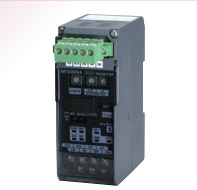
MITSUBISHI
NZ2AW1C1BY Bridge module
MITSUBISHI NZ2AW1C1BY Manual And Instructions
NZ2AW1C1BY datasheetPDF datasheet
MITSUBISHI NZ2AW1C1BY Product information and technical parameters:
Brand: MITSUBISHI
Name: Bridge module
Model: NZ2AW1C1BY
CC-LINK-AnyWire Bitty bridge module.
...More relevant models >>>>
NZ2AW1C1BY datasheetPDF datasheet
MITSUBISHI NZ2AW1C1BY Product information and technical parameters:
Brand: MITSUBISHI
Name: Bridge module
Model: NZ2AW1C1BY
CC-LINK-AnyWire Bitty bridge module.
Input type: DC input, positive common end.
Input points: 16 points.
Enter the response time: 1.5ms the following.
Rated input voltage / current: DC24V/5mA.
External connection: 3 wire.
Spring clip terminal.
Do not need to be tightened further or locked with screws, which can reduce the working hours of wiring NZ2AW1C1BY.
Using 2 pieces of structure of the terminal units, maintenance can be maintained in the same line under the condition of the replacement module NZ2AW1C1BY
When installing the module can choose to use the DIN guide rail or screw mounting.
Can be used for the 3 wire sensor input wiring. Input type: DC input, positive public end / negative public end.
Input points: 32 points.
Enter the response time: 0 NZ2AW1C1BY. 2ms below, below 1.5ms, 5ms below, 10ms the following.
Rated input voltage / current: DC24V/7mA.
External connection: 1 wire.
According to the external connection mode and the external equipment input and output specifications,
Choose from a rich product lineup.
Finger protection through the upper part of the terminal,
The human body will not be exposed to live parts,
Therefore, the terminal station type remote I/O module can be directly mounted to the machine tool NZ2AW1C1BY. Number of channels: RS422, 1 channel
.
Configuration of master / local station,
In addition to the other site network with different CC-Link in addition to the main station and the remote station configuration can also be the main station and the local station configuration.
A local PLC can communicate with the master station PLC and other remote workstations.
MITSUBISHI PLC online debugging.
On-line debugging is the process that will through the simulation debugging to further carry on the on-line unification to adjust.
On-line debugging process should be step by step,
From MITSUBISHI PLC only connected to the input device, and then connect the output device, and then connect to the actual load and so on and so on step by step.
If you do not meet the requirements, the hardware and procedures for adjustment.
Usually only need to modify the part of the program can be.
MITSUBISHI PLC hardware implementation
Hardware implementation is mainly for the control cabinet and other hardware design and field construction.
Design control cabinet and the operating table and other parts of tthe electrical wiring diagram and wiring diagram NZ2AW1C1BY.
Electrical interconnection diagram of each part of the design system.
According to the construction drawings of the site wiring, and carry out a detailed inspection.
Because the program deesign and hardware implementation can be carried out at the same time,
So the design cycle of the MITSUBISHI PLC control system can be greatly reduced NZ2AW1C1BY.
...More relevant models >>>>