 LK Automation Limited
Brand:
MITSUBISHI
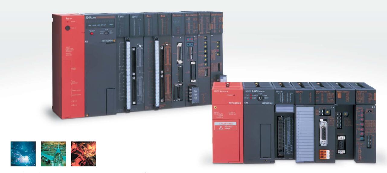
AJ71QC24-R2 Serial communication module
MITSUBISHI AJ71QC24-R2 Manual And Instructions
AJ71QC24-R2 datasheetPDF datasheet
AJ71QC24-R2 HardwareUser's Manual
AJ71QC24-R2 HardwareUser's Manual
AJ71QC24-R2 Modem Function Additional VersionUser's Manual
MITSUBISHI AJ71QC24-R2 Product information and technical parameters:
Brand: MITSUBISHI
Name: Serial communication module
Model: AJ71QC24-R2
RS-232 2 channel.
Transfer speed: 0.3-19.2kbps.
Equipment layer / field bus CC-Link device layer is the PLC and other control devices and sensors and drive devices connected to the field network,
Network for the lowest layer of the whole network system.
Using CC-Link field bus connection, the number of wiring is greatly reduced,
Improve the maintainability of the system.
And, not just the amount of data ON/OFF and other switches,
Can also be connected to the ID system, bar code reader, inverter, man-machine interface and other intelligent devices,
From the completion of a variety of data communication, the management of the terminal production information can be realized,
On the centralized management of the state of the machine movement,
Make maintenance work efficiency also greatly improved.
Q series PLC in the use of CC-Link function better,
And easier to use.
...More relevant models >>>>
AJ71QC24-R2 datasheetPDF datasheet
AJ71QC24-R2 HardwareUser's Manual
AJ71QC24-R2 HardwareUser's Manual
AJ71QC24-R2 Modem Function Additional VersionUser's Manual
MITSUBISHI AJ71QC24-R2 Product information and technical parameters:
Brand: MITSUBISHI
Name: Serial communication module
Model: AJ71QC24-R2
RS-232 2 channel.
Transfer speed: 0.3-19.2kbps.
Equipment layer / field bus CC-Link device layer is the PLC and other control devices and sensors and drive devices connected to the field network,
Network for the lowest layer of the whole network system.
Using CC-Link field bus connection, the number of wiring is greatly reduced,
Improve the maintainability of the system.
And, not just the amount of data ON/OFF and other switches,
Can also be connected to the ID system, bar code reader, inverter, man-machine interface and other intelligent devices,
From the completion of a variety of data communication, the management of the terminal production information can be realized,
On the centralized management of the state of the machine movement,
Make maintenance work efficiency also greatly improved.
Q series PLC in the use of CC-Link function better,
And easier to use.
10BASE5/10BASE2
Control layer /MELSECNET/10 (H) is the middle layer of the whole network system,
Control network which is convenient and high speed processing data transmission between PLC, CNC and other control equipment.
As MELSEC control network MELSECNET/10,
With its good real-time performance, simple network settings, no procedures of the network data sharing concept,
As well as the redundant circuit and so on, has obtained the very high market appraisal,
The number of devices to reach the highest in japan,
In the world is also one of the few AJ71QC24-R2 AJ71QC24-R2
And MELSECNET/H not only inherited the excellent characteristics of MELSECNET/10,
Also makes the network real-time better, more data capacity,
Further adapt to the needs of the market AJ71QC24-R2. 16 channels.
Thermocouple input.
38 point terminal station.
Thermocouple I/P multiplex unit.
Detailed analysis of the process and work characteristics of the controlled object,
To understand the coordination between the controlled object machine, electricity and liquid,
The control requirements of the controlled object for MITSUBISHI PLC control system are put forward,
Determine the control program, to develop a design task book AJ71QC24-R2.
How to determine the input / output device of MITSUBISHI plc.
According to the control requirements of the system,
All input devices and output devices required for the determination of the system,
To determine the input / output device related to the MITSUBISHI PLC,
To determine the I/O PLC points. 2 slots.
Can be installed in the power supply unit for A series units installed QnA/.
Cannot extend.
Relay output interface circuit of PLC
Working process: when the internal circuit output digital signal 1,
There is a current flowing through, the relay coil has a current, and then the normally open contact is closed,
Provide load current and voltage.
When the internal circuit outputs a digital signal 0, there is no current flowing through it,
The relay coil does not have a current, and the normally open contact is broken off,
A current or voltage that is disconnected from the load.
It is through the output interface circuit to the internal digital circuit into a signal to make the load action or not action.
I/O points is an important indicator of PLC.
Reasonable selection of I/O points can not only satisfy the control requirements of the system,
And the total investment of the system is the lowest.
The input and output points and types of PLC should be determinedd according to the analog quantity and switch quantity of the controlled object,
Generally an input / output element to take up an input / output point AJ71QC24-R2.
Taking into account the future adjustment and expansion,
In general should be estimaated on the total number of points plus the amount of spare 20%~30% AJ71QC24-R2.
The following describes the centralized control system I/O points of the estimate.
...More relevant models >>>>