 LK Automation Limited
Brand:
MITSUBISHI
AJ71BR11 Coaxial cable module
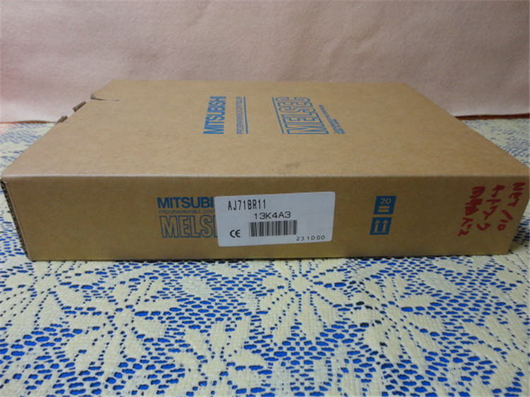
MITSUBISHI AJ71BR11 Manual And Instructions
AJ71BR11 datasheetPDF datasheet
AJ71BR11 Reference Manual
AJ71BR11 PLC to PLC networkReference Manual
AJ71BR11 Reference Manual
AJ71BR11 Reference Manual
MITSUBISHI AJ71BR11 Product information and technical parameters:
Brand: MITSUBISHI
Name: Coaxial cable module
Model: AJ71BR11
3C-2V/5C-2V coaxial cable.
Single bus.
PC inter network (management station / station) / remote I/O network (remote control station).
How to choose MITSUBISHI PLC.
MITSUBISHI PLC options include the choice of MITSUBISHI PLC models, capacity, I/O module, power, etc..
MITSUBISHI PLC distribution I/O points and design MITSUBISHI PLC peripheral hardware circuit
Draw the I/O point of the PLC and the input / output device connection diagram or the corresponding table,
This part also can be carried out in second steps.
Design PLC peripheral hardware circuit.
Draw the electrical wiring diagram of the other parts of the system,
Including the main circuit and the control circuit does not enter the PLC, etc..
The electrical schematic diagram of the system composed of I/O PLC connection diagram and PLC peripheral electrical circuit diagram.
So far the system''s hardware electrical circuit has been determined.
...More relevant models >>>>
AJ71BR11 datasheetPDF datasheet
AJ71BR11 Reference Manual
AJ71BR11 PLC to PLC networkReference Manual
AJ71BR11 Reference Manual
AJ71BR11 Reference Manual
MITSUBISHI AJ71BR11 Product information and technical parameters:
Brand: MITSUBISHI
Name: Coaxial cable module
Model: AJ71BR11
3C-2V/5C-2V coaxial cable.
Single bus.
PC inter network (management station / station) / remote I/O network (remote control station).
How to choose MITSUBISHI PLC.
MITSUBISHI PLC options include the choice of MITSUBISHI PLC models, capacity, I/O module, power, etc..
MITSUBISHI PLC distribution I/O points and design MITSUBISHI PLC peripheral hardware circuit
Draw the I/O point of the PLC and the input / output device connection diagram or the corresponding table,
This part also can be carried out in second steps.
Design PLC peripheral hardware circuit.
Draw the electrical wiring diagram of the other parts of the system,
Including the main circuit and the control circuit does not enter the PLC, etc..
The electrical schematic diagram of the system composed of I/O PLC connection diagram and PLC peripheral electrical circuit diagram.
So far the system''s hardware electrical circuit has been determined.
Input and output points: 480 points.
Program capacity: 7K step.
Basic command processing speed: 4.4 ~ 5.6us.
Power supply: input DC5V output 2A DC24V/.
Modular: PLC is the basic components of a separate module.
Medium and large PLC used this way. Easy maintenance.
Relay output interface circuit of PLC
Working process: when the internal circuit output digital signal 1,
There is a current flowing through, the relay coil has a current, and then the normally open contact is closed,
Provide load current and voltage AJ71BR11 AJ71BR11
When the internal circuit outputs a digital signal 0, there is no current flowing through it,
The relay coil does not have a current, and the normally open contact is broken off,
A current or voltage that is disconnected from the load AJ71BR11.
It is through the output interface circuit to the internal digital circuit into a signal to make the load action or not action.
User program storage capacity: it is a measure of how much the user application can store the number of indicators.
Usually in words or K words as units. 16 bit binary number is a word,
Every 1024 words are 1K words AJ71BR11. PLC to store instructions and data in words.
General logical operation instructions each account for 1 words. Timer / counter,
Shift instruction accounted for 2 words. Data operation instructions for 2~4.
Can connect the transmitter units 2 units using radius of about 50 meters (outdoor 200 meters).
According to the control requirements of the system, using the appropriate design method to design MITSUBISHI PLC program.
Procedures to meet the requirements of system control as the main line,
Write one by one to achieve the control function or the sub task of the program,
Gradually improve the functions specified by the system.
MITSUBISHI PLC initialization procedure AJ71BR11. After MITSUBISHI PLC on power, the general need to do some of the initial operation,
In order to start making necessary preparations, to avoid the wrong operation of the system.
The main contents of the initialization program arre: to some data area, counter and so on,
Data needed to restore some of the data area,
Set or reset some relays,
For some initial state display, etc AJ71BR11. .
...More relevant models >>>>