 LK Automation Limited
Brand:
MITSUBISHI
AI61-S1 Interrupt module
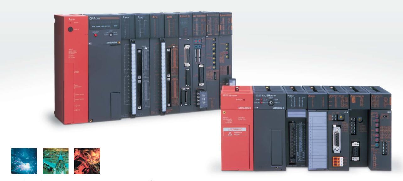
MITSUBISHI AI61-S1 Manual And Instructions
AI61-S1 datasheetPDF datasheet
MITSUBISHI AI61-S1 Product information and technical parameters:
Brand: MITSUBISHI
Name: Interrupt module
Model: AI61-S1
Enter 16 points.
Voltage and current: 14mA DC24V.
Response time: 8ms.
16 point 1 public end, 20 point terminal.
Detailed analysis of the process and work characteristics of the controlled object,
To understand the coordination between the controlled object machine, electricity and liquid,
The control requirements of the controlled object for MITSUBISHI PLC control system are put forward,
Determine the control program, to develop a design task book.
How to determine the input / output device of MITSUBISHI plc.
According to the control requirements of the system,
All input devices and output devices required for the determination of the system,
To determine the input / output device related to the MITSUBISHI PLC,
To determine the I/O PLC points.
...More relevant models >>>>
AI61-S1 datasheetPDF datasheet
MITSUBISHI AI61-S1 Product information and technical parameters:
Brand: MITSUBISHI
Name: Interrupt module
Model: AI61-S1
Enter 16 points.
Voltage and current: 14mA DC24V.
Response time: 8ms.
16 point 1 public end, 20 point terminal.
Detailed analysis of the process and work characteristics of the controlled object,
To understand the coordination between the controlled object machine, electricity and liquid,
The control requirements of the controlled object for MITSUBISHI PLC control system are put forward,
Determine the control program, to develop a design task book.
How to determine the input / output device of MITSUBISHI plc.
According to the control requirements of the system,
All input devices and output devices required for the determination of the system,
To determine the input / output device related to the MITSUBISHI PLC,
To determine the I/O PLC points.
Input and output points: 2048 points.
Input / output data points: 8192 points.
Program capacity: 92k.
Basic command processing speed (LD command) S:0.15.
The length of time required to execute the instruction, the length of the user''s program, the type of instruction, and the speed of the CPU execution are very significant,
Generally, a scanning process, the fault diagnosis time,
Communication time, input sampling and output refresh time is less,
The execution time is accounted for the vast majority of AI61-S1 AI61-S1
The photoelectric coupler is composed of two luminous two extreme tubes and a photoelectric transistor.
Light emitting diode two: the input of a photo coupler and the change of electrical signal,
The light signal is generated by the light emitting diode, which is the same as the input signal AI61-S1.
The working process of the input interface circuit: when the switch is closed, the diode light,
The transistor is then guided to the internal circuit and input signal under the irradiation of the light.
When the switch is off, the diode does not emit light, and the transistor is not on the way AI61-S1. Internal circuit input signal.
It is through the input interface circuit to the external switch signal into PLC internal can accept the digital signal.
Photoelectric three levels: in the light of the light signal conduction, the degree of light signal and the intensity of the light signal.
The output signal has a linear relationship with the input signal in the linear operating region of the photoelectric coupler.
User program storage capacity: it is a measure of how much the user application can store the number of indicators.
Usually in words or K words as units. 16 bit binary number is a word,
Every 1024 words are 1K words. PLC to store instructions and data in words.
General logical operation instructions each account for 1 words. Timer / counter,
Shift instruction accounted for 2 words. Data operation instructions for 2~4.
Input points: 32 points.
Input voltage: DC12V/DC24V.
Current: 3/7mA.
Response time: 10ms.
16 points / a common end.
Positive pole sharing.
50 point terminal station.
System program memory for storing system program,
Including management procedures, monitoring procedures, as well as the user program to do the compiler to compile the process of interpretation.
Read only memory. Manufacturers use, content can not be changed, power does not disappear.
PLC selection with the development of PLC technology, more and more types of PLC products,
Function is becoming more and more perfect, and its application is more and more extensive.
Different series of different models of PLC has different performance, applicable occasions also have different emphasis,
Price also has a greater difference. Therefore PLC selection,
Under the premise of meeting the control requirements,
Should consider the best performance to price ratio, a reasonable choice of PLC.
Each scanning process. Focus on the input signal sampling. Focus on the output signal to refresh.
Input refresh process. When the input port is closed,
Program in the implementation phase, the input end of a new state, the new state can not be read.
Only when the program is scanned, the new state is read.
A scan cycle is divided into the input sample, the program execution, the output refresh.
The contents of the component image register are changed with the change of the execution of the program AI61-S1.
The length of the scan cycle is determined by the three.
CPU the speed of executing instructions.
Time of instruction.
Instruction count.
Due to thhe adoption of centralized sampling AI61-S1.
Centralized output mode.
There exist input / output hysteresis phenomena, i.e., the input / output response delay.
...More relevant models >>>>