 LK Automation Limited
Brand:
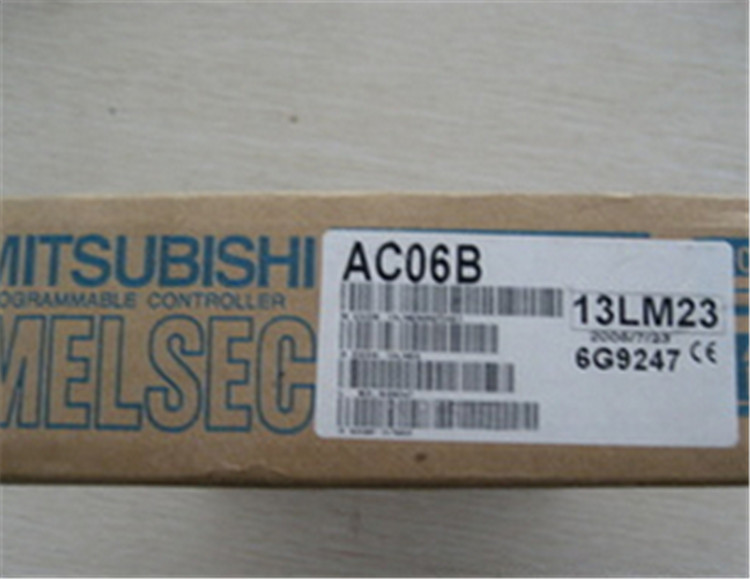
MITSUBISHI
AC06B Extension cable
MITSUBISHI AC06B Manual And Instructions
AC06B datasheetPDF datasheet
MITSUBISHI AC06B Product information and technical parameters:
Brand: MITSUBISHI
Name: Extension cable
Model: AC06B
Cable 0.6m for the expansion of the floor, the expansion of a floor for every 1 units.
...More relevant models >>>>
AC06B datasheetPDF datasheet
MITSUBISHI AC06B Product information and technical parameters:
Brand: MITSUBISHI
Name: Extension cable
Model: AC06B
Cable 0.6m for the expansion of the floor, the expansion of a floor for every 1 units.
Input and output points: 512 points.
Input / output data points: 512 points.
Program capacity: 14K.
Basic command processing speed (LD command) s:1.0.
User program storage capacity: it is a measure of how much the user application can store the number of indicators.
Usually in words or K words as units AC06B. 16 bit binary number is a word,
Every 1024 words are 1K words. PLC to store instructions and data in words AC06B
General logical operation instructions each account for 1 words. Timer / counter,
Shift instruction accounted for 2 words. Data operation instructions for 2~4.
Integral type: the PLC components are installed together or a few pieces of printed circuit board,
And together with the power supply installed in the casing to form a single overall called the host or the basic unit, small, ultra small PLC using this structure AC06B.
Modular: PLC is the basic components of a separate module.
Medium and large PLC used this way. Easy maintenance. SI/QSI/H-PCF/ wide range H-PCF fiber optic cable.
Double loop.
PC inter network (management station / station) / remote I/O network (remote control station) AC06B.
How to choose MITSUBISHI PLC.
MITSUBISHI PLC options include the choice of MITSUBISHI PLC models, capacity, I/O module, power, etc..
MITSUBISHI PLC distribution I/O points and design MITSUBISHI PLC peripheral hardware circuit
Draw the I/O point of the PLC and the input / output device connection diagram or the corresponding table,
This part also can be carried out in second steps.
Design PLC peripheral hardware circuit.
Draw the electrical wiring diagram of the other parts of the system,
Including the main circuit and the control circuit does not enter the PLC, etc..
The electrical schematic diagram of the system composed of I/O PLC connection diagram and PLC peripheral electrical circuit diagram.
So far the system''s hardware electrical circuit has been determined. 3C-2V/5C-2V coaxial cable.
Double circuit.
MELSECNET (II) (Master / local station).
According to the control requirements of the system, using the appropriate design method to design MITSUBISHI PLC program.
Procedures to meet the requirements of system control as the main line,
Write one by one to achieve the control function or the sub task of the program,
Gradually improve the functions specified by the system.
MITSUBISHI PLC initializatiion procedure AC06B. After MITSUBISHI PLC on power, the general need to do some of the initial operation,
In order to start making necessary preparations, to avoid the wrong operation of the system.
The main contents of the initialization program arre: to some data area, counter and so on,
Data needed to restore some of the data area,
Set or reset some relays,
For some initial state display, etc AC06B. .
...More relevant models >>>>