 LK Automation Limited
Brand:
MITSUBISHI
A67P Power module
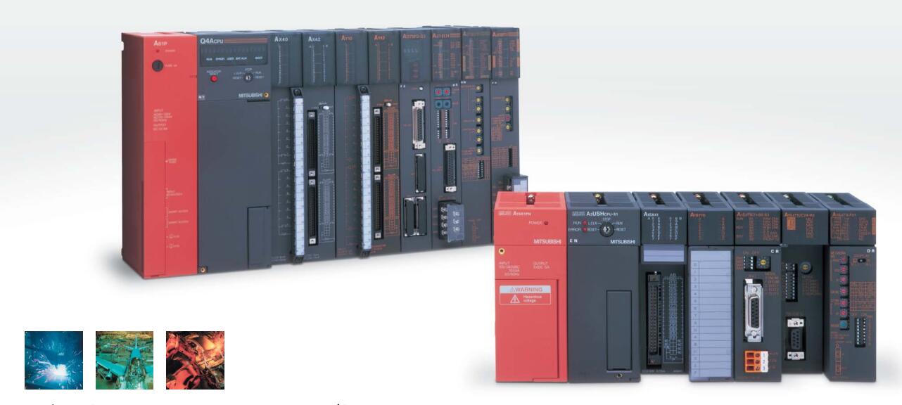
MITSUBISHI A67P Manual And Instructions
A67P datasheetPDF datasheet
MITSUBISHI A67P Product information and technical parameters:
Brand: MITSUBISHI
Name: Power module
Model: A67P
Input voltage range: DC110V.
Output voltage: DC5V.
Output current: 8A.
I/O points is an important indicator of PLC.
Reasonable selection of I/O points can not only satisfy the control requirements of the system,
And the total investment of the system is the lowest.
The input and output points and types of PLC should be determined according to the analog quantity and switch quantity of the controlled object,
Generally an input / output element to take up an input / output point.
Taking into account the future adjustment and expansion,
In general should be estimated on the total number of points plus the amount of spare 20%~30%.
The following describes the centralized control system I/O points of the estimate.
...More relevant models >>>>
A67P datasheetPDF datasheet
MITSUBISHI A67P Product information and technical parameters:
Brand: MITSUBISHI
Name: Power module
Model: A67P
Input voltage range: DC110V.
Output voltage: DC5V.
Output current: 8A.
I/O points is an important indicator of PLC.
Reasonable selection of I/O points can not only satisfy the control requirements of the system,
And the total investment of the system is the lowest.
The input and output points and types of PLC should be determined according to the analog quantity and switch quantity of the controlled object,
Generally an input / output element to take up an input / output point.
Taking into account the future adjustment and expansion,
In general should be estimated on the total number of points plus the amount of spare 20%~30%.
The following describes the centralized control system I/O points of the estimate.
RS-232:1, RS-422/485:1.
Transmission speed: 0.3 ~ 19.2kpbs.
Computer connection function.
Design PLC peripheral hardware circuit.
Draw the electrical wiring diagram of the other parts of the system,
Including the main circuit and the control circuit does not enter the PLC, etc..
The electrical schematic diagram of the system composed of I/O PLC connection diagram and PLC peripheral electrical circuit diagram A67P A67P
So far the system''s hardware electrical circuit has been determined.
Printer / peripheral device connection, BASIC language function.
How to choose MITSUBISHI PLC.
MITSUBISHI PLC options include the choice of MITSUBISHI PLC models, capacity, I/O module, power, etc..
MITSUBISHI PLC distribution I/O points and design MITSUBISHI PLC peripheral hardware circuit
Draw the I/O point of the PLC and the input / output device connection diagram or the corresponding table,
This part also can be carried out in second steps A67P. Master / local station.
QnACPU use.
According to the control requirements of the system, using the appropriate design method to design MITSUBISHI PLC program.
Procedures to meet the requirements of system control as the main line,
Write one by one to achieve the control function or the sub task of the program,
Gradually improve the functions specified by the system A67P.
MITSUBISHI PLC initialization procedure. After MITSUBISHI PLC on power, the general need to do some of the initial operation,
In order to start making necessary preparations, to avoid the wrong operation of the system.
The main contents of the initialization program are: to some data area, counter and so on,
Data needed to restore some of the data area,
Set or reset some relays,
For some initial state display, etc.. "A3VTS using the basic unit.
Relay output interface circuit of PLC
Working process: when the internal circuit output digital signal 1,
There is a current flowing through, the relay coil has a current, and then the normally open contact is closed,
Provide load current and voltage.
When the internal circuit outputs a digital signal 0, there is no current flowing through it,
The relay coil does not have a current, and the normally open contact is broken off,
A current or voltage that is disconnected from the load.
It is through the output interface circuit to the internal digital circuit into a signal to make the load action or not action.
When the programmer input programinto the user program memory,
Then CPU according to the function of the system (the system program memory to explain the compiler),
Translate the user program into PLC internally recognized by the user to compile the program.
I/O points is an important indicator of PLC.
Reasonable selection of I/O points can not only satisfy the control requirements of the system,
And the total investment of the system is the lowest.
The input and output points and types of PLC should be dettermined according to the analog quantity and switch quantity of the controlled object,
Generally an input / output element to take up an input / output point A67P.
Taking into account the future adjustment and expansion,
In general should be estimaated on the total number of points plus the amount of spare 20%~30% A67P.
The following describes the centralized control system I/O points of the estimate.
...More relevant models >>>>