 LK Automation Limited
Brand:
MITSUBISHI
A65P Power module
MITSUBISHI A65P Manual And Instructions
A65P datasheetPDF datasheet
MITSUBISHI A65P Product information and technical parameters:
Brand: MITSUBISHI
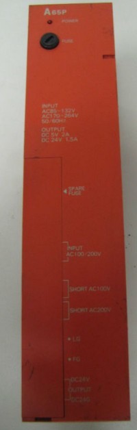
Name: Power module
Model: A65P
Input voltage range: AC100-120V/AC200-240V.
Output voltage: DC5/24V.
Output current: 2/1.5A.
PLC selection with the development of PLC technology, more and more types of PLC products,
Function is becoming more and more perfect, and its application is more and more extensive.
Different series of different models of PLC has different performance, applicable occasions also have different emphasis,
Price also has a greater difference. Therefore PLC selection,
Under the premise of meeting the control requirements,
Should consider the best performance to price ratio, a reasonable choice of PLC.
...More relevant models >>>>
A65P datasheetPDF datasheet
MITSUBISHI A65P Product information and technical parameters:
Brand: MITSUBISHI
Name: Power module
Model: A65P
Input voltage range: AC100-120V/AC200-240V.
Output voltage: DC5/24V.
Output current: 2/1.5A.
PLC selection with the development of PLC technology, more and more types of PLC products,
Function is becoming more and more perfect, and its application is more and more extensive.
Different series of different models of PLC has different performance, applicable occasions also have different emphasis,
Price also has a greater difference. Therefore PLC selection,
Under the premise of meeting the control requirements,
Should consider the best performance to price ratio, a reasonable choice of PLC.
RS-232:1, RS-422/485:1.
Transmission speed: 0.3 ~ 19.2kpbs.
Computer connection function.
So far the system''s hardware electrical circuit has been determined.
Printer / peripheral device connection, BASIC language function.
How to choose MITSUBISHI PLC.
MITSUBISHI PLC options include the choice of MITSUBISHI PLC models, capacity, I/O module, power, etc A65P. .
MITSUBISHI PLC distribution I/O points and design MITSUBISHI PLC peripheral hardware circuit
Draw the I/O point of the PLC and the input / output device connection diagram or the corresponding table,
This part also can be carried out in second steps A65P
Design PLC peripheral hardware circuit.
Draw the electrical wiring diagram of the other parts of the system,
Including the main circuit and the control circuit does not enter the PLC, etc A65P. .
The electrical schematic diagram of the system composed of I/O PLC connection diagram and PLC peripheral electrical circuit diagram. Fiber optic cable / twisted pair cable.
Single bus.
Remote I/O station.
According to the control requirements of the system, using the appropriate design method to design MITSUBISHI PLC program A65P.
Procedures to meet the requirements of system control as the main line,
Write one by one to achieve the control function or the sub task of the program,
Gradually improve the functions specified by the system.
MITSUBISHI PLC initialization procedure. After MITSUBISHI PLC on power, the general need to do some of the initial operation,
In order to start making necessary preparations, to avoid the wrong operation of the system.
The main contents of the initialization program are: to some data area, counter and so on,
Data needed to restore some of the data area,
Set or reset some relays,
For some initial state display, etc.. Input points: 32 points.
Voltage: AC200 ~ 240V.
Current: 10mA.
Response time: 25ms.
32 points / a common end..
38 point terminal station.
System program memory for storing system program,
Including management procedures, monitoring procedures, as well as the user program to do the compiler to compile the process of interpretation.
Read only memory. Manufacturers use, content can not be changed, power does not disappear.
PLC selection with the development of PLC technology, more and more types of PLC products,
Function is becoming more and more perfect, and its application is more and more extensive.
Different series of different models of PLC has different performance, applicable occasions also have different emphasis,
Price also has a greater difference. Therefore PLC selection,
Under the premise of meeting the control requirements,
Should consider the best performance to price ratio, a reasonable choice of PLC.
Each scanning process. Focus on the input signal sampling. Focus on the output signal to refresh.
Input refresh process. When the input port is closed,
Program in the implementation phase, the input end of a new state, the new state can not be read.
Only when the program is scanned, the new state is read.
A scan cycle is divided into the input sample, the program execution, the output refresh.
The contennts of the component image register are changed with the change of the execution of the program A65P.
The length of the scan cycle is determined by the three.
CPU the speed of executing instructions.
Time of instruction.
Instruction count.
Due to thhe adoption of centralized sampling A65P.
Centralized output mode.
There exist input / output hysteresis phenomena, i.e., the input / output response delay.
...More relevant models >>>>