 LK Automation Limited
Brand:
MITSUBISHI
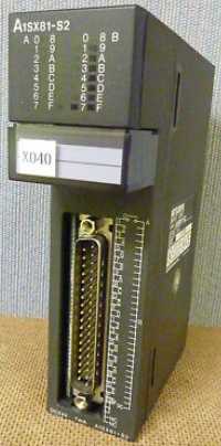
A1SX81-S2 DC source type input module
MITSUBISHI A1SX81-S2 Manual And Instructions
A1SX81-S2 datasheetPDF datasheet
A1SX81-S2 User's Manual
MITSUBISHI A1SX81-S2 Product information and technical parameters:
Brand: MITSUBISHI
Name: DC source type input module
Model: A1SX81-S2
Type of input: DC source.
Input points: 32 points.
Input voltage: DC24.
Input current: 7mA.
Connection mode: terminal row.
Common common point: 32.
Sequential function flow chart language is designed to satisfy the sequential logic control.
The process of sequential process action is divided into steps and transformation conditions,
According to the transfer condition, the control system is distributed in the function flow sequence,
Step by step according to the sequence of actions.
Each step represents a control function, represented by the box.
In the box, the ladder logic is used to complete the task of the corresponding control function.
This programming language makes the program structure clear and easy to read and maintain,
Greatly reduce the programming workload, shorten the programming and debugging time.
Used in the system of the size of the school, procedures for more complex occasions.
Sequence function flow chart programming language features: to function as the main line, in accordance with the functional flow of the order of distribution, clear, easy to understand the user program,
Avoid the defect of ladder diagram or other languages,
At the same time, the use of ladder language to avoid the use of ladder programming,
Due to the complicated mechanical interlock, the structure of the user program is complex and difficult to understand,
User program scan time is also greatly reduced.
...More relevant models >>>>
A1SX81-S2 datasheetPDF datasheet
A1SX81-S2 User's Manual
MITSUBISHI A1SX81-S2 Product information and technical parameters:
Brand: MITSUBISHI
Name: DC source type input module
Model: A1SX81-S2
Type of input: DC source.
Input points: 32 points.
Input voltage: DC24.
Input current: 7mA.
Connection mode: terminal row.
Common common point: 32.
Sequential function flow chart language is designed to satisfy the sequential logic control.
The process of sequential process action is divided into steps and transformation conditions,
According to the transfer condition, the control system is distributed in the function flow sequence,
Step by step according to the sequence of actions.
Each step represents a control function, represented by the box.
In the box, the ladder logic is used to complete the task of the corresponding control function.
This programming language makes the program structure clear and easy to read and maintain,
Greatly reduce the programming workload, shorten the programming and debugging time.
Used in the system of the size of the school, procedures for more complex occasions.
Sequence function flow chart programming language features: to function as the main line, in accordance with the functional flow of the order of distribution, clear, easy to understand the user program,
Avoid the defect of ladder diagram or other languages,
At the same time, the use of ladder language to avoid the use of ladder programming,
Due to the complicated mechanical interlock, the structure of the user program is complex and difficult to understand,
User program scan time is also greatly reduced.
Using A6SIM-X64Y64 simulation I/O module in the system before the connection can be carried out to control the process of debugging.
The simulation unit consists of 16 blocks of 4 switches and 4 LED LEDs. RS-232 1 channel.
RS-422/485 1 channel.
Transmission speed: 2 channels.
At the same time the use of 115 A1SX81-S2. 2kbps may.
When the programmer input programinto the user program memory,
Then CPU according to the function of the system (the system program memory to explain the compiler),
Translate the user program into PLC internally recognized by the user to compile the program A1SX81-S2
Input status and input information input from the input interface,
CPU will be stored in the working data memory or in the input image register A1SX81-S2.
And then combine the data and the program with CPU.
The result is stored in the output image register or the working data memory,
And then output to the output interface, control the external drive.
Semiconductor circuit with memory function.
System program memory and user memory.
System program memory for storing system program,
Including management procedures, monitoring procedures, as well as the user program to do the compiler to compile the process of interpretation A1SX81-S2.
Read only memory. Manufacturers use, content can not be changed, power does not disappear.
User memory: user program storage area and work data storage area.
Composed of random access memory (RAM). User use.
Power cut off. Commonly used efficient lithium battery as a backup power supply, life is generally 3~5 years. Type of input: DC leakage.
Input points: 32 points.
Input voltage: DC24.
Input current: 7mA.
Connection mode: terminal row.
Common common point: 32.
Functional block diagram language is a kind of PLC programming language, which is similar to digital logic circuit.
The function module is used to represent the function of the module,
Different function modules have different functions.
Functional module figure programming language features: functional block diagram programming language is characterized by a functional module for the unit,
Analysis and understanding of the contrrol scheme is simple and easy: function module is to use graphical form of expression,
Intuitive, for a digital logic circuit based on the design of the staff is very easy to master the programming;
Control system with complex scale and coomplex control logic,
Because the function module diagram can clearly express the function relation, the programming debugging time is greatly reduced A1SX81-S2 A1SX81-S2.
...More relevant models >>>>