 LK Automation Limited
Brand:
MITSUBISHI
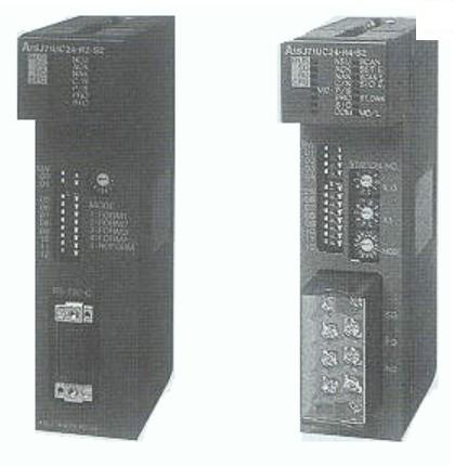
A1SJ71UC24-R2-S2 MODBUS interface module
MITSUBISHI A1SJ71UC24-R2-S2 Manual And Instructions
A1SJ71UC24-R2-S2 datasheetPDF datasheet
A1SJ71UC24-R2-S2 User's Manual
MITSUBISHI A1SJ71UC24-R2-S2 Product information and technical parameters:
Brand: MITSUBISHI
Name: MODBUS interface module
Model: A1SJ71UC24-R2-S2
Data format: ASCII.
Data bits: 7.
A1SJ71UC24-R2-S2 and A1SJ71UC24-R4-S2 allow the Ans series PLC to be connected to the MODBUS network,
As the network from the station, and in accordance with the instructions of the main station of the CPU Ans user storage area for data reading / writing.
In addition to supporting the MODBUS protocol, these components also support the standard dedicated communication protocol for A1SJ71UC24 components.
This feature makes the main station of the data acquisition and control with more flexibility.
Support MODBUS slave station protocol.
Supports 1 to 21 function code.
Two transmission modes: RTU or ASCII.
...More relevant models >>>>
A1SJ71UC24-R2-S2 datasheetPDF datasheet
A1SJ71UC24-R2-S2 User's Manual
MITSUBISHI A1SJ71UC24-R2-S2 Product information and technical parameters:
Brand: MITSUBISHI
Name: MODBUS interface module
Model: A1SJ71UC24-R2-S2
Data format: ASCII.
Data bits: 7.
A1SJ71UC24-R2-S2 and A1SJ71UC24-R4-S2 allow the Ans series PLC to be connected to the MODBUS network,
As the network from the station, and in accordance with the instructions of the main station of the CPU Ans user storage area for data reading / writing.
In addition to supporting the MODBUS protocol, these components also support the standard dedicated communication protocol for A1SJ71UC24 components.
This feature makes the main station of the data acquisition and control with more flexibility.
Support MODBUS slave station protocol.
Supports 1 to 21 function code.
Two transmission modes: RTU or ASCII.
Type of input: DC leakage.
Input points: 16 points.
Input voltage: DC24.
Input current: 7mA.
Connection mode: terminal row.
Common common point: 16.
The instruction list programming language is a programming language similar to assembly language mnemonic,
As well as assembly language by the operation code and the number of operations A1SJ71UC24-R2-S2.
In the case of the computer for the PLC handheld programmer compile user program A1SJ71UC24-R2-S2
At the same time, the programming language of the instruction list corresponds to the ladder diagram programming language,
In PLC programming software can be converted to each other. Figure 3 is the instruction sheet corresponding to the ladder diagram of figure 2PLC.
The characteristics of instruction table programming language is used to represent mnemonic operation function,
Easy to remember, easy to grasp;
In the handheld programmer on the keyboard using the mnemonic representation, easy to operate, can be programmed in computer;
There is a one-to-one correspondence between the ladder diagram and the ladder diagram A1SJ71UC24-R2-S2. Its characteristics are basically consistent with the ladder diagram language A1SJ71UC24-R2-S2. Temperature sensor: PT100, 3 wire system.
The A1S62RD3 and A1S62RD4 temperature sensor input modules allow the platinum resistance temperature sensing element to be directly connected to the PLC,
This component converts a signal from a temperature measuring element to a numeric value that represents a temperature measurement value,
This temperature value can be used for the control process.
The length of time required to execute the instruction, the length of the user''s program, the type of instruction, and the speed of the CPU execution are very significant,
Generally, a scanning process, the fault diagnosis time,
Communication time, input sampling and output refresh time is less,
The execution time is accounted for the vast majority of.
The response time of PLC is the interval between the time of the change of the external output signal of the PLC and the time of the change of the external output signal which is controlled by it,
Lag time, this is the time constant of the input circuit,
The time constant of the output circuit, the arrangement of the user statement and the usse of the instruction,
The cycle scan mode of PLC and the way of PLC to refresh the I/O and so on A1SJ71UC24-R2-S2 A1SJ71UC24-R2-S2.
This phenomenon is called the I/O delay time effect.
...More relevant models >>>>