Brand:
MITSUBISHI
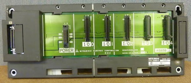
A1S65B-S1 Expansion substrate capable of mounting power supply
MITSUBISHI A1S65B-S1 Manual And Instructions
A1S65B-S1 datasheetPDF datasheet
MITSUBISHI A1S65B-S1 Product information and technical parameters:
Brand: MITSUBISHI
Name: Expansion substrate capable of mounting power supply
Model: A1S65B-S1
I/O slots: 5 slots.
Could you install the power module.
Outline dimension: 315*130.
There are two types of extended floor,
A power module can be inserted, and the other one is not.
The choice of any type of substrate depends on the total DC5V current consumption and the power supply on the CPU main substrate.
If the total demand is less than the power output, no additional power supply,
Then you can choose a more economical expansion board.
Both ends of the main base plate of the CPU have an expansion interface, and can be used for extending the cable connection.
...More relevant models >>>>
A1S65B-S1 datasheetPDF datasheet
MITSUBISHI A1S65B-S1 Product information and technical parameters:
Brand: MITSUBISHI
Name: Expansion substrate capable of mounting power supply
Model: A1S65B-S1
I/O slots: 5 slots.
Could you install the power module.
Outline dimension: 315*130.
There are two types of extended floor,
A power module can be inserted, and the other one is not.
The choice of any type of substrate depends on the total DC5V current consumption and the power supply on the CPU main substrate.
If the total demand is less than the power output, no additional power supply,
Then you can choose a more economical expansion board.
Both ends of the main base plate of the CPU have an expansion interface, and can be used for extending the cable connection.
Number of channels: 2 channels.
Sensing method and temperature range: PT100.
A1S64TC series component is a kind of temperature controller combined with ANS series CPU.
Components with temperature measurement input and built-in PID algorithm control output, can be used in a variety of temperature control occasions A1S65B-S1.
Each component controls up to 4 loops at most.
Thermocouple input or PT100 3 wire temperature sensor input A1S65B-S1
Control output switching signal for the output of the transistor.
BW is a signal with broken line detection function. 4 channel analog input module.
A1S64AD analog input module can accept the voltage or current signal,
The built-in microprocessor converts these signals to binary values,
For the control program to enjoy A1S65B-S1.
Signal can be instantaneous read, can also be programmed time / frequency average,
The offset and gain value can be set, and this component also includes the following performance:
4 input channels.
High resolution digital output.
Total accuracy plus or minus 1%. 2 channel analog output module.
As well as analog input modules, the A1S62DA analog output component is built into a microprocessor,
It can convert binary data into voltage or current signals,
Offset and gain are set and stored in a microprocessor,
It also includes other features as follows:
2 output channels A1S65B-S1.
High resolution digital input, plus or minus 12000.
Total accuracy plus or minus 1%. Input and output points: 1024 points.
Input / output data points: 8192 points.
Program capacity: 60k.
Basic command processing speed (LD command) S:0.2.
PLC in the program execution stage: according to the order of the user program order to store the order of each instruction,
After the corresponding operation and processing, the reesult is written to the output status register,
The contents of the output status register are changed with the execution of the program A1S65B-S1.
Output refresh phase: when all instructions are executed,
The output status register is sent to the ooutput latch in the output refresh stage,
And through a certain way (relay, transistor or transistor) output, drive the corresponding output equipment A1S65B-S1.
...More relevant models >>>>

