 LK Automation Limited
Brand:
MITSUBISHI
A1S42X Input module
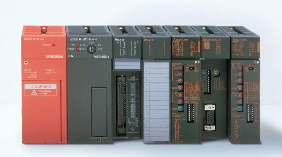
MITSUBISHI A1S42X Manual And Instructions
A1S42X datasheetPDF datasheet
MITSUBISHI A1S42X Product information and technical parameters:
Brand: MITSUBISHI
Name: Input module
Model: A1S42X
...More relevant models >>>>
A1S42X datasheetPDF datasheet
MITSUBISHI A1S42X Product information and technical parameters:
Brand: MITSUBISHI
Name: Input module
Model: A1S42X
SRAM memory card.
RAM capacity: 512KB. The main unit of the AS-i system
The response time of PLC is the interval between the time of the change of the external output signal of the PLC and the time of the change of the external output signal which is controlled by it,
Lag time, this is the time constant of the input circuit,
The time constant of the output circuit, the arrangement of the user statement and the use of the instruction,
The cycle scan mode of PLC and the way of PLC to refresh the I/O and so on A1S42X A1S42X
This phenomenon is called the I/O delay time effect.
Input status and input information input from the input interface,
CPU will be stored in the working data memory or in the input image register A1S42X.
And then combine the data and the program with CPU.
The result is stored in the output image register or the working data memory,
And then output to the output interface, control the external drive. SRAM memory card.
RAM capacity: 1MB. Signal transmission device B/NET interface device for power distribution control equipment
The response time of PLC is the interval between the time of the change of the external output signal of the PLC and the time of the change of the external output signal which is controlled by it,
Lag time, this is the time constant of the input circuit,
The time constant of the output circuit, the arrangement of the user statement and the use of the instruction,
The cycle scan mode of PLC and the way of PLC to refresh the I/O and so on A1S42X.
This phenomenon is called the I/O delay time effect.
Input status and input information input from the input interface,
CPU will be stored in the working data memory or in the input image register.
And then combine the data and the program with CPU.
The result is stored in the output image register or the working data memory,
And then output to the output interface, control the external drive. Type of input: DC leakage.
Input points: 64 points.
Input voltage: DC24.
Input current: 5mA.
Connection mode: terminal row.
Common common point: 32.
Functional block diagram language is a kind of PLC programming language, which is similar to digital logic circuit.
The function module is used to represent the function of the module,
Different function modules have different functions.
Functional module figure programming language features: functional block diagram programming language is characterized by a functional module for the unit,
Analysis and understanding of the coontrol scheme is simple and easy: function module is to use graphical form of expression,
Intuitive, for a digital logic circuit based on the design of the staff is very easy to master the programming;
Control system with complex scale and coomplex control logic,
Because the function module diagram can clearly express the function relation, the programming debugging time is greatly reduced A1S42X A1S42X.
...More relevant models >>>>