 LK Automation Limited
Brand:
MITSUBISHI
A0J2P25 Network module
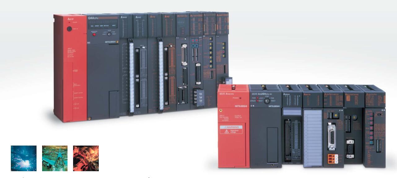
MITSUBISHI A0J2P25 Manual And Instructions
A0J2P25 datasheetPDF datasheet
MITSUBISHI A0J2P25 Product information and technical parameters:
Brand: MITSUBISHI
Name: Network module
Model: A0J2P25
SI-200/250 fiber optic cable.
Double loop.
Remote station.
According to the control requirements of the system, using the appropriate design method to design MITSUBISHI PLC program.
Procedures to meet the requirements of system control as the main line,
Write one by one to achieve the control function or the sub task of the program,
Gradually improve the functions specified by the system.
MITSUBISHI PLC initialization procedure. After MITSUBISHI PLC on power, the general need to do some of the initial operation,
In order to start making necessary preparations, to avoid the wrong operation of the system.
The main contents of the initialization program are: to some data area, counter and so on,
Data needed to restore some of the data area,
Set or reset some relays,
For some initial state display, etc..
...More relevant models >>>>
A0J2P25 datasheetPDF datasheet
MITSUBISHI A0J2P25 Product information and technical parameters:
Brand: MITSUBISHI
Name: Network module
Model: A0J2P25
SI-200/250 fiber optic cable.
Double loop.
Remote station.
According to the control requirements of the system, using the appropriate design method to design MITSUBISHI PLC program.
Procedures to meet the requirements of system control as the main line,
Write one by one to achieve the control function or the sub task of the program,
Gradually improve the functions specified by the system.
MITSUBISHI PLC initialization procedure. After MITSUBISHI PLC on power, the general need to do some of the initial operation,
In order to start making necessary preparations, to avoid the wrong operation of the system.
The main contents of the initialization program are: to some data area, counter and so on,
Data needed to restore some of the data area,
Set or reset some relays,
For some initial state display, etc..
Input and output points: 1024 points.
Input / output data points: 8192 points.
Program capacity: 60k.
Basic command processing speed (LD command) S:0.2.
The length of time required to execute the instruction, the length of the user''s program, the type of instruction, and the speed of the CPU execution are very significant,
Generally, a scanning process, the fault diagnosis time,
Communication time, input sampling and output refresh time is less,
The execution time is accounted for the vast majority of A0J2P25 A0J2P25
The photoelectric coupler is composed of two luminous two extreme tubes and a photoelectric transistor.
Light emitting diode two: the input of a photo coupler and the change of electrical signal,
The light signal is generated by the light emitting diode, which is the same as the input signal A0J2P25.
The working process of the input interface circuit: when the switch is closed, the diode light,
The transistor is then guided to the internal circuit and input signal under the irradiation of the light.
When the switch is off, the diode does not emit light, and the transistor is not on the way A0J2P25. Internal circuit input signal.
It is through the input interface circuit to the external switch signal into PLC internal can accept the digital signal.
Photoelectric three levels: in the light of the light signal conduction, the degree of light signal and the intensity of the light signal.
The output signal has a linear relationship with the input signal in the linear operating region of the photoelectric coupler.
User program storage capacity: it is a measure of how much the user application can store the number of indicators.
Usually in words or K words as units. 16 bit binary number is a word,
Every 1024 words are 1K words. PLC to store instructions and data in words.
General logical operation instructions each account for 1 words. Timer / counter,
Shift instruction accounted for 2 words. Data operation instructions for 2~4. 16 channels.
Input: DC-10 ~ 10V, DC-20 ~ 20mA.
Output (resolution): 0 ~ 4000, 0 ~ 8000, 0 ~ 12000.
38 point terminal station.
Analog I/P multiplexing unit.
Detailed analysis of the process and work characteristics of the controlled object,
To understand the coordination between the controlled object machine, electricity and liquid,
The control requirements of the controlled object for MITSUBISHI PLC conttrol system are put forward,
Determine the control program, to develop a design task book A0J2P25.
How to determine the input / output device of MITSUBISHI plc.
According to the control requirements of the system,
All input devices and output devicees required for the determination of the system,
To determine the input / output device related to the MITSUBISHI PLC,
To determine the I/O PLC points A0J2P25.
...More relevant models >>>>