Brand Sort:
MITSUBISHI
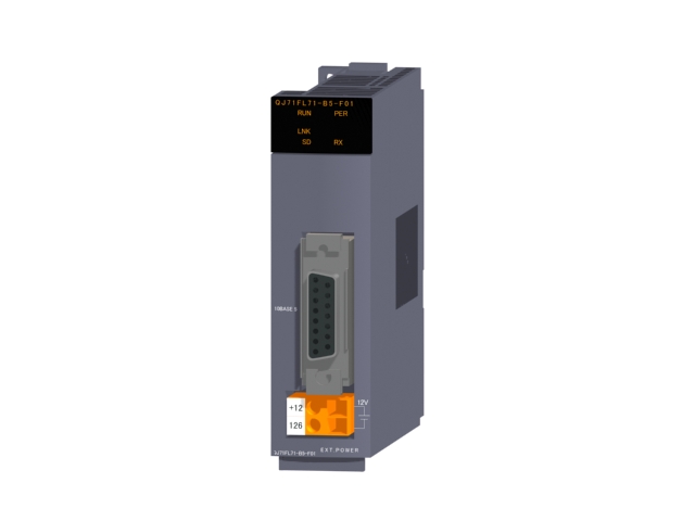
MITSUBISHI QJ71FL71-B5-F01 Price
- Brand: MITSUBISHI
- Country: JAPAN
- Name: FL-net module
- Model: QJ71FL71-B5-F01
- Price: U.S.$ 338.98
MITSUBISHI QJ71FL71-B5-F01
For video input (NTCS/PAL) 4 channel / RGB input 1 channel composite input.
Applicable model: GT16. Hardware implementation is mainly to control cabinet and other hardware design and field construction.
Design control cabinet and the operating table and other parts of the electrical wiring diagram and wiring diagram.
Electrical interconnection diagram of each part of the design system.
According to the construction drawings of the site wiring, and carry out a detailed inspection QJ71FL71-B5-F01
Because the program design and hardware implementation can be carried out at the same time,
So the design cycle of the MITSUBISHI PLC control system can be greatly reduced. In FX1NC, FX2NC, PLC FX3U connection FX0N, FX2N with the expansion of the device when.
Conversion adapter to use. Open collector output.
Axis of control: 2.
Maximum output pulse: pulse/s 200k.
Location data: 600 data / axis.
Max link distance: 2m.
With the parameter setting, the synchronization control can be easily realized. Do not need to write complex procedures.
Start / stop with synchronous control of the shaft.
Synchronous control of the axis and the positioning of the axis can coexist.
Through the clutch, the movement of the main shaft can be transferred to the output shaft.
Simple implementation of synchronization control.
Cam control is more simple
Cam data can easily create a variety of patterns.
Can be simple to achieve the gear, shaft, transmission, cam and other mechanical mechanisms to replace the software synchronization control.
It is not subject to the limitation of the concept of the electronic cam control so far, and can use the cam with high degree of freedom.
The stroke, speed, acceleration and beat can be confirmed on the graph, and the setting is carried out at the same time.
Can also be through the cam data thumbnail display, easy to confirm the cam data has been created.
Can import and export the cam data in CSV format. Category: Master station.
Transfer speed: 125kbps/250kbps/500kbps/1Mbps.
Transmission line form: bus system.
Total distance: 125kbps:1000m/250kbps:800m/500kbps:480m/1Mbps:240m.
The maximum connection units: 32.
Total points: input + output <=2048 point.
MITSUBISHI PLC detection, fault diagnosis and display and other procedures.
These procedures are relatively independent, generally in the basic completion of the program design and then add.
MITSUBISHI PLC protection and chain procedures.
Protection and chain is an indispensable part of the program, must be carefully considered.
It can avoid the control logic confusion caused by illegal operations.
QJ71FL71-B5-F01 Operation manual/Instructions/Model selection sample download link: /searchDownload.html?Search=QJ71FL71-B5-F01&select=5
...more relevant model market price >>>>
Related products
MITSUBISHI
FL-net module
QJ71FL71-T-F01
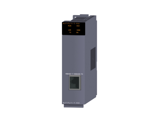
FL-net OPCN-2 Ver.2.00 interface.
10BA
MITSUBISHI
FL-net module
QJ71FL71-B5
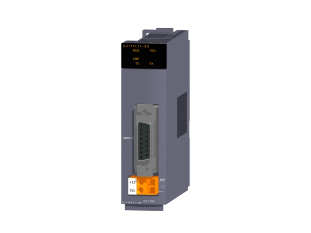
FL-net OPCN-2 Ver.1.00 interface.
10BA
MITSUBISHI
FL-net module
QJ71FL71-B2
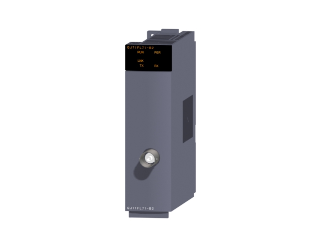
FL-net OPCN-2 Ver.1.00 interface.
10BA
MITSUBISHI
FL-net module
QJ71FL71-B2-F01
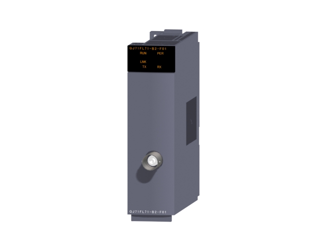
FL-net OPCN-2 Ver.2.00 interface.
10BA

