Brand Sort:
MITSUBISHI
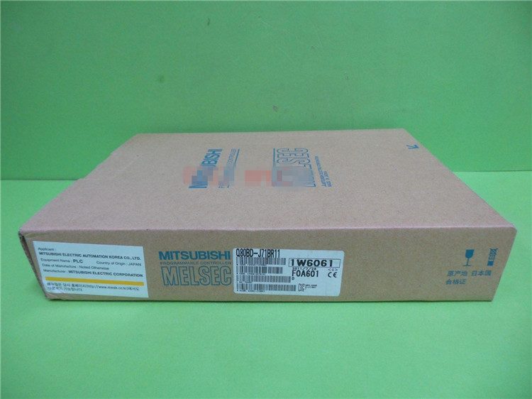
MITSUBISHI Q80BD-J71LP21G Price
- Brand: MITSUBISHI
- Country: JAPAN
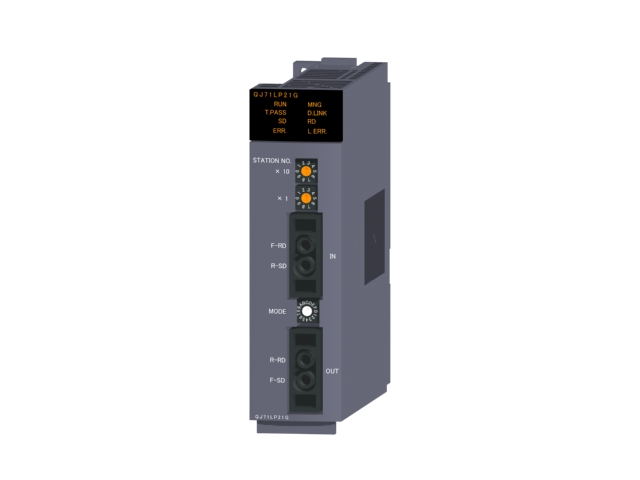
- Name: Optical fiber loop (GI) module
- Model: Q80BD-J71LP21G
- Price: U.S.$ 3777.97
MITSUBISHI Q80BD-J71LP21G
1 axis servo amplifier.
MITSUBISHI general AC servo amplifier MELSERVO-J4 series.
Rated output: 0.4kw.
Interface: SSCNET III /H.
Power supply: three phase AC200V or single phase AC200V power supply.
Single phase AC200V is limited to 0.75kW following servo amplifier.
Servo amplifier supporting SSCNET III /H.
Complete synchronization system capable of using high speed serial optical communication.
Can be combined with the servo system controller to maximize the performance of the servo system Q80BD-J71LP21G
MELSERVO-J4 grand debut.
Servo market for the star of tomorrow. World class servo products.
The new generation of MELSERVO should be what kind of? The answer to this question is already floating
Out of the water. MELSERVO-J4, it represents the whole digital, the original high performance based on an evolutionary.
Is also fully meet the requirements of human beings and the environment MELSERVO latest masterpiece.
For example, the safety and environmental requirements for the safety of human use and the safety specifications and "to Use Easy" design.
To meet the needs of the environmental protection era of energy-saving performance.
Beyond the performance of the evolution of MELSERVO-J4, shocking debut!Screw, 2 piece type terminal
Platinum temperature measuring resistor body PT100 temperature input module.
Number of channels: 4 channels.
Number of stations: 4 stops.
Station type: remote equipment station.
MITSUBISHI PLC online debugging.
On-line debugging is the process that will through the simulation debugging to further carry on the on-line unification to adjust.
On-line debugging process should be step by step,
From MITSUBISHI PLC only connected to the input device, and then connect the output device, and then connect to the actual load and so on and so on step by step.
If you do not meet the requirements, the hardware and procedures for adjustment.
Usually only need to modify the part of the program can be.
MITSUBISHI PLC hardware implementation
Hardware implementation is mainly for the control cabinet and other hardware design and field construction.
Design control cabinet and the operating table and other parts of the electrical wiring diagram and wiring diagram.
Electrical interconnection diagram of each part of the design system.
According to the construction drawings of the site wiring, and carry out a detailed inspection.
Because the program design and hardware implementation can be carried out at the same time,
So the design cycle of the MITSUBISHI PLC control system can be greatly reduced.
Q80BD-J71LP21G Operation manual/Instructions/Model selection sample download link: /searchDownload.html?Search=Q80BD-J71LP21G&select=5
...more relevant model market price >>>>
Related products
MITSUBISHI
Optical fiber loop (GI) module
QJ71LP21G

GI-50/125 optical cale.
Doule ring.
PL
MITSUBISHI
CC-Link module
Q80BD-J61BT11N

PCI us.
Support Japanese, English OS.
M
MITSUBISHI
Coaxial bus module
Q80BD-J71BR11

PCI us.
Support Japanese, English OS.
3


