Brand Sort:
MITSUBISHI
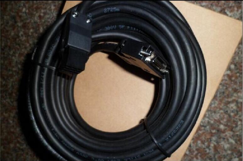
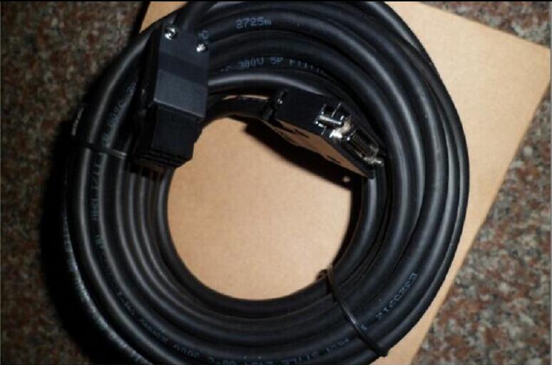
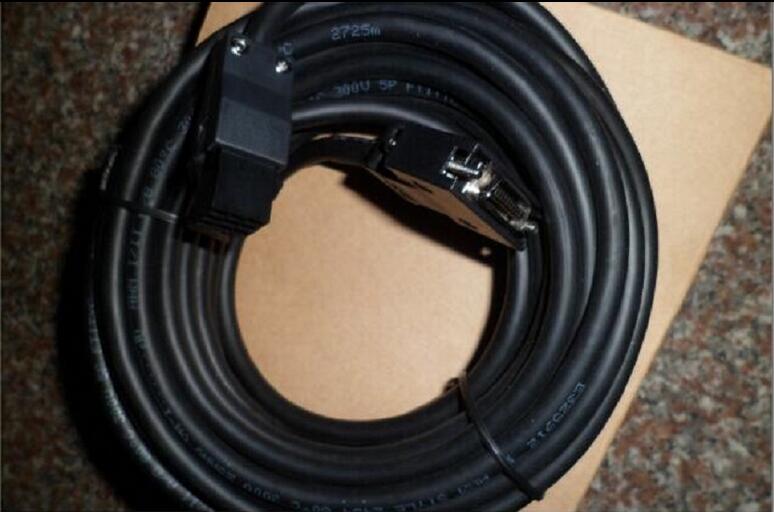
MITSUBISHI MR-J3ENCBL20M-A1-L Price

- Brand: MITSUBISHI
- Country: JAPAN
- Name:
- Model: MR-J3ENCBL20M-A1-L
- Price: 0 >
MITSUBISHI MR-J3ENCBL20M-A1-L
Servo motor series: medium inertia, medium power.
Rated output: 2.0kw.
Rated speed: 1000r/min.
Electromagnetic brake: with.
Shaft end specification: Standard (straight axis).
Characteristics: medium inertia has two types of low speed and high speed, suitable for different applications.
IP level: IP67.
Application example:
1, material handling system.
2, industrial robots.
3, X-Y working table.
The protection level of the HF-SP/HF-JP series servo motor is IP67 (except the shaft part) MR-J3ENCBL20M-A1-L
Motor capacity selection soft (MRZJW3-MOTSZ111E)
Friendly interface design, only in the mechanical description window input constant and operation mode can choose the best servo amplifier,
The servo motor and the regenerative braking options, but also in the selection window in the selection of linear servo motor and direct drive motor.
Characteristic
(1) 10 typical mechanical transmission structure can be used to choose
(2) user defined operating modes (location and speed control)
(3) in the selection process, the feed speed and torque can be displayed in a graphical format.
(4) the calculation process can be displayed
Can easily calculate the power of the servo motor free software!Function: input / output module (internal service power supply).
Input / output points: 32 points
Input points: 16 points.
Output points: 16 points.
DC5V internal consumption current: 965mA.
DC24V internal consumption current: 250mA.
Input / output mode: DC input (drain / source) / transistor (drain).
In order to extend the input output of the device.
Also has a built-in power supply products.
The maximum number of points for the input and output is 256.
Expansion module: up to 16 units (in addition to the power expansion module)
The total number of CC-Link, AnyWireASLINK, and Bitty series of remote I/O is 512 points. 8 slots.
Power supply unit.
QnAS series unit installation.
High speed access.
I/O points is an important indicator of PLC.
Reasonable selection of I/O points can not only satisfy the control requirements of the system,
And the total investment of the system is the lowest.
The input and output points and types of PLC should be determined according to the analog quantity and switch quantity of the controlled object,
Generally an input / output element to take up an input / output point.
Taking into account the future adjustment and expansion,
In general should be estimated on the total number of points plus the amount of spare 20%~30%.
When the programmer input programinto the user program memory,
Then CPU according to the function of the system (the system program memory to explain the compiler),
Translate the user program into PLC internally recognized by the user to compile the program.
Relay output interface circuit of PLC
Working process: when the internal circuit output digital signal 1,
There is a current flowing through, the relay coil has a current, and then the normally open contact is closed,
Provide load current and voltage.
When the internal circuit outputs a digital signal 0, there is no current flowing through it,
The relay coil does not have a current, and the normally open contact is broken off,
A current or voltage that is disconnected from the load.
It is through the output interface circuit to the internal digital circuit into a signal to make the load action or not action.
MR-J3ENCBL20M-A1-L Operation manual/Instructions/Model selection sample download link: /searchDownload.html?Search=MR-J3ENCBL20M-A1-L&select=5
...more relevant model market price >>>>
Related products
MITSUBISHI
Encoder cable
MR-J3ENCBL10M-A2-H

The length of the line: 10M.
IP level: I
MITSUBISHI
Encoder cable
MR-J3ENCBL2M-A1-L

The length of the line: 2M.
IP level: IP
MITSUBISHI
Encoder cable
MR-J3ENCBL10M-A1-L

The length of the line: 10M.
IP level: I
MITSUBISHI
Encoder cable
MR-J3ENCBL5M-A2-H

The length of the line: 5M.
IP level: IP
