Brand Sort:
MITSUBISHI
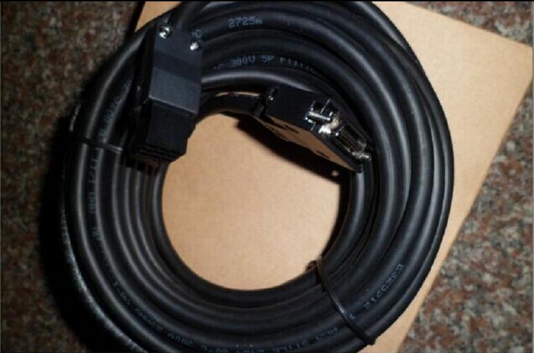
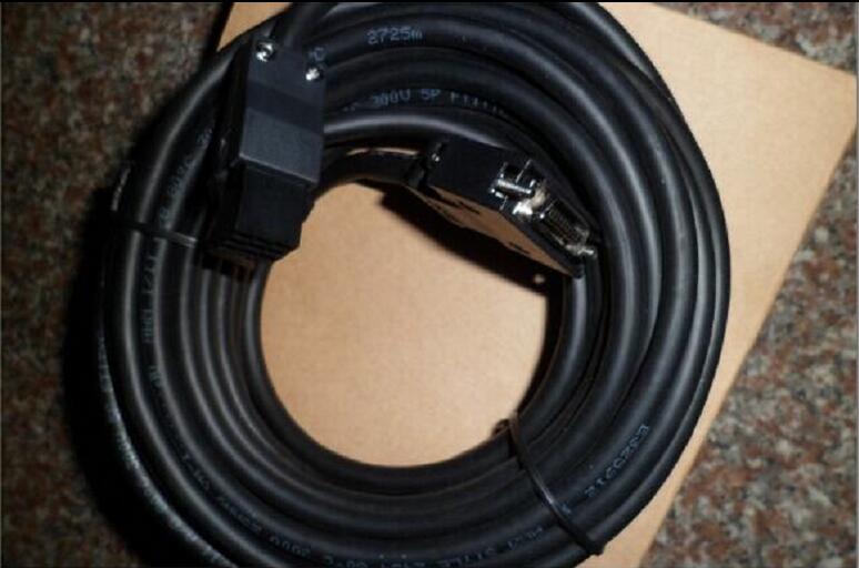
MITSUBISHI MR-BKS1CBL10M-A2-L Price
- Brand: MITSUBISHI
- Country: JAPAN
- Name: Cable for electromagnetic brake
- Model: MR-BKS1CBL10M-A2-L
- Price: U.S.$ 89.83
MITSUBISHI MR-BKS1CBL10M-A2-L
Servo motor series: low inertia, medium / high power.
Rated output: 0.5kw.
Rated speed: 3000r/min.
Electromagnetic brake: No.
Shaft end specification: Standard (straight axis).
Voltage: 400V level.
Features: low inertia for high speed / acceleration and deceleration operation occasions.
IP level: IP67.
Application example:
1, food processing machinery.
2, printing machine.
3, injection molding machine (11KW, 15KW) MR-BKS1CBL10M-A2-L
4, large press machine (11KW, 15KW).
The protection level of the HF-SP/HF-JP series servo motor is IP67 (except the shaft part).
Low inertia of the power servo motor (0.5kW ~ 9kW), the maximum speed: 6000r/min (rated speed: 3000r/min),
Suitable for high frequency positioning and acceleration / deceleration operations, especially for food processing machines and printing machines.
Low inertia, high power, no cooling fan servo motor (11kW and 15kW), maximum speed: 3000r/min (rated speed: 1500r/min).
The motor structure is more compact due to the adoption of the non cooling fan design, and the connection is reduced by using the power source connector.
(compared with the HF-LP series servo motor with the same power, the volume is reduced by about 46%, and the weight is reduced by about 34%,
Suitable for high frequency positioning and acceleration / deceleration operations, especially for injection molding machines and large presses.
HF-JP703 (4) /903 (4) maximum speed: 5000r/min. Remote I/O controller, optical fiber.
How to choose MITSUBISHI PLC.
MITSUBISHI PLC options include the choice of MITSUBISHI PLC models, capacity, I/O module, power, etc..
MITSUBISHI PLC distribution I/O points and design MITSUBISHI PLC peripheral hardware circuit
Draw the I/O point of the PLC and the input / output device connection diagram or the corresponding table,
This part also can be carried out in second steps.
Design PLC peripheral hardware circuit.
Draw the electrical wiring diagram of the other parts of the system,
Including the main circuit and the control circuit does not enter the PLC, etc..
The electrical schematic diagram of the system composed of I/O PLC connection diagram and PLC peripheral electrical circuit diagram.
So far the system''s hardware electrical circuit has been determined.
MR-BKS1CBL10M-A2-L Operation manual/Instructions/Model selection sample download link: /searchDownload.html?Search=MR-BKS1CBL10M-A2-L&select=5
...more relevant model market price >>>>
Related products
MITSUBISHI
Cable for electromagnetic brake
MR-BKS1CBL5M-A1-H
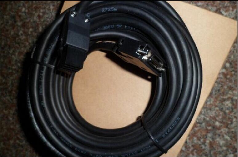
The length of the line: 5M.
IP level: IP
MITSUBISHI
Cable for electromagnetic brake
MR-BKS1CBL10M-A2-H
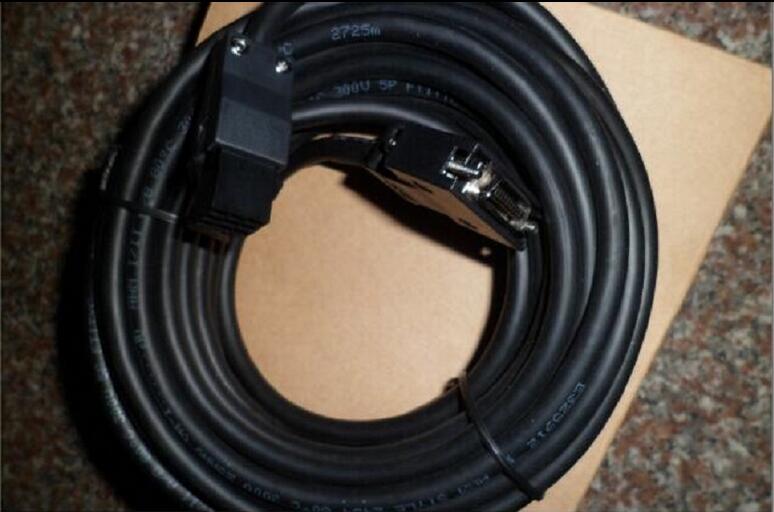
The length of the line: 10M.
IP level: I
MITSUBISHI
Cable for power supply of servo motor
MR-PWS1CBL10M-A2-L
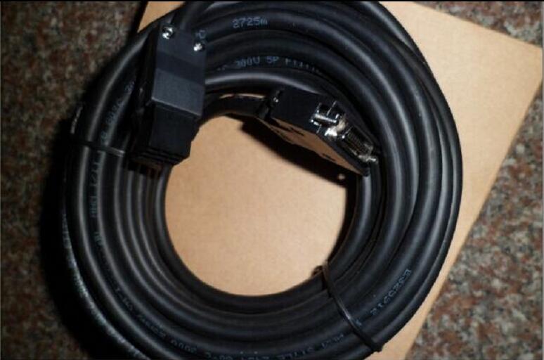
The length of the line: 10M.
IP level: I
MITSUBISHI
Encoder cable
MR-J3ENCBL10M-A2-L
The length of the line: 10M.
IP level: I

