Brand Sort:
MITSUBISHI
MITSUBISHI HF-KP053K Price
- Brand: MITSUBISHI
- Country: JAPAN
- Name: Low inertia small power servo motor
- Model: HF-KP053K
- Price: U.S.$ 579.66
MITSUBISHI HF-KP053K
Cable length: 10 meters.
For QnA/A/FX (FX1, FX2, FX2C) CPU and GOT connection between.
For connection between FA-CNV_CBL and GOT.
For connection between FX-2PIF and GOT.
For connection between FX-422AW0 and GOT.
For serial communication module AJ71QC24 (N) -R4 and GOT connection between.
For connection between AJ65BT-G4-S3 and GOT. Input and output points: 48 points.
DC power supply: DC24V.
Input points: 24 points HF-KP053K
Output points: 24 points.
Output form: relay output.
Weight: 0.85kg.
Input signal voltage: DC24V.
FX2N series expansion unit
Expansion unit is an input and output expansion device with a built-in power supply.
As with the basic unit, the extension unit can be connected to a variety of input and output and special extension equipment.
Can connect to FX3GA/FX3G, FX3GE and FX3U.
AC power model, the built-in maximum DC24V 250mA/460mA supply power.
Because all models of FX series are built in high speed counter,
So the high speed control can be realized by the simple procedure.
The input of the basic unit is built in the anti jitter filter,
One part as digital filter,
Sensitivity adjustment unit can reach 1ms.
Using high speed counter automatically adjusted to the minimum value.
Through the high cost of the built-in positioning function and the expansion function to increase the number of control axis.
Extended function expansion board and special adapter,
Data links and communication with external serial devices. Function extension board for USB communication.
DC5V power consumption: 0mA. Cable flat cable;
Connector with 20 pin installed at both ends of the fuse.
Length 3M. Input channel number: 4.
Output channel number: 2.
Occupy I/O points: 64.
A1S63ADA analog input / output combination components can be analog / digital / digital / analog conversion,
The input and output signals can be voltage or current,
Offset and gain can be set and stored.
The length of time required to execute the instruction, the length of the user''s program, the type of instruction, and the speed of the CPU execution are very significant,
Generally, a scanning process, the fault diagnosis time,
Communication time, input sampling and output refresh time is less,
The execution time is accounted for the vast majority of.
The response time of PLC is the interval between the time of the change of the external output signal of the PLC and the time of the change of the external output signal which is controlled by it,
Lag time, this is the time constant of the input circuit,
The time constant of the output circuit, the arrangement of the user statement and the use of the instruction,
The cycle scan mode of PLC and the way of PLC to refresh the I/O and so on.
This phenomenon is called the I/O delay time effect.
HF-KP053K Operation manual/Instructions/Model selection sample download link: /searchDownload.html?Search=HF-KP053K&select=5
...more relevant model market price >>>>
Related products
MITSUBISHI
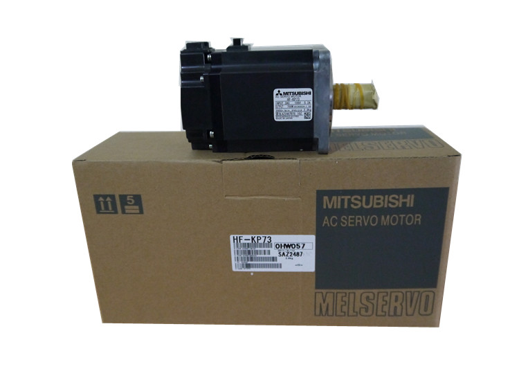
Low inertia small power servo motor
HF-KP73

Servo motor series: low inertia, low pow
MITSUBISHI
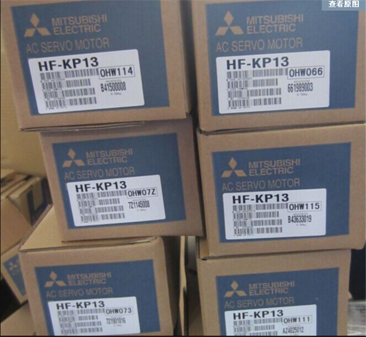
Low inertia small power servo motor
HF-KP13

Servo motor series: low inertia, low pow
MITSUBISHI
General motors for MR-JE and MR-E
HF-KN73BJ-S100

Type: HF-KN servo motor, low inertia, lo
MITSUBISHI
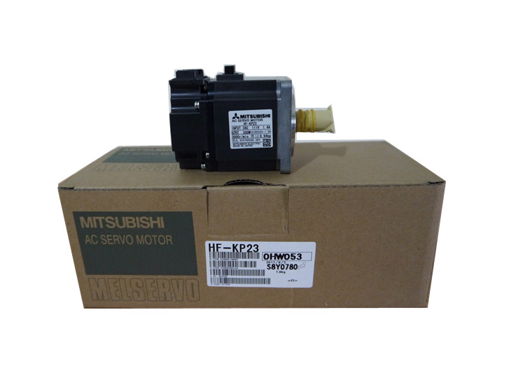
Low inertia small power servo motor
HF-KP23

Servo motor series: low inertia, low pow

