Brand Sort:
MITSUBISHI
MITSUBISHI HC-RFS203BG2 1/29 Price

- Brand: MITSUBISHI
- Country: JAPAN
- Name:
- Model: HC-RFS203BG2 1/29
- Price: U.S.$ 10530.51
MITSUBISHI HC-RFS203BG2 1/29
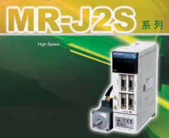
MITSUBISHI motor universal AC servo amplifier MELSERVO-J3 series.
Rated output: 0.4kw.
Interface type: CC-Link communication type (built-in positioning function).
Power specification: single phase AC100V.
Positioning operation by setting position and rotational speed data in the positioning table and receiving the start signal from the main controller.
The setting of the position and speed of the positioning table, as well as the start and stop operation can be completed through CC-Link communication HC-RFS203BG2 1/29
By using the MR-J3-D01 extension IO unit, the DI/O instruction can be used to select and locate the table.
(CC-Link can not be used for MR-J3-D01 communications).
With built-in positioning function of the servo amplifier, can be set through the CC-Link communications and speed data. (corresponding to the CC-Link version: Ver.1.10)
Can be achieved through the CC-Link communications to start, stop and monitoring and other operations.
Serial communication reduce wiring.
Distributed servo control system can be built by CC-Link communication.
The parameters of unit MR-PRU03 (optional) the parameter setting, operation and monitoring more convenient.
The servo amplifier can be used for speed control operation.
When the two stations are occupied, the speed can be set directly by the remote register. Pulse input: differential input.
Preset input: differential input.
Count range: 0~16777215.
Number of stations: 4 stops.
Station type: remote equipment station.
Configuration of master / local station,
In addition to the other site network with different CC-Link in addition to the main station and the remote station configuration can also be the main station and the local station configuration.
A local PLC can communicate with the master station PLC and other remote workstations.
MITSUBISHI PLC hardware implementation
Hardware implementation is mainly for the control cabinet and other hardware design and field construction.
Design control cabinet and the operating table and other parts of the electrical wiring diagram and wiring diagram.
Electrical interconnection diagram of each part of the design system.
According to the construction drawings of the site wiring, and carry out a detailed inspection.
Because the program design and hardware implementation can be carried out at the same time,
So the design cycle of the MITSUBISHI PLC control system can be greatly reduced.
MITSUBISHI PLC online debugging.
On-line debugging is the process that will through the simulation debugging to further carry on the on-line unification to adjust.
On-line debugging process should be step by step,
From MITSUBISHI PLC only connected to the input device, and then connect the output device, and then connect to the actual load and so on and so on step by step.
If you do not meet the requirements, the hardware and procedures for adjustment.
Usually only need to modify the part of the program can be.
HC-RFS203BG2 1/29 Operation manual/Instructions/Model selection sample download link: /searchDownload.html?Search=HC-RFS203BG2 1/29&select=5
...more relevant model market price >>>>
Related products
MITSUBISHI
Ultra low inertia medium power motor
HC-RFS203

Motor series: super low inertia, medium
MITSUBISHI
Ultra low inertia medium power motor
HC-RFS203B

Motor series: super low inertia, medium
MITSUBISHI
Ultra low inertia medium power motor
HC-RFS203K

Motor series: super low inertia, medium
