Brand Sort:
MITSUBISHI
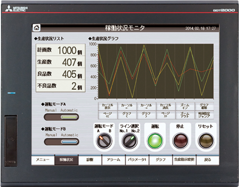
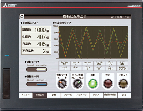
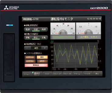
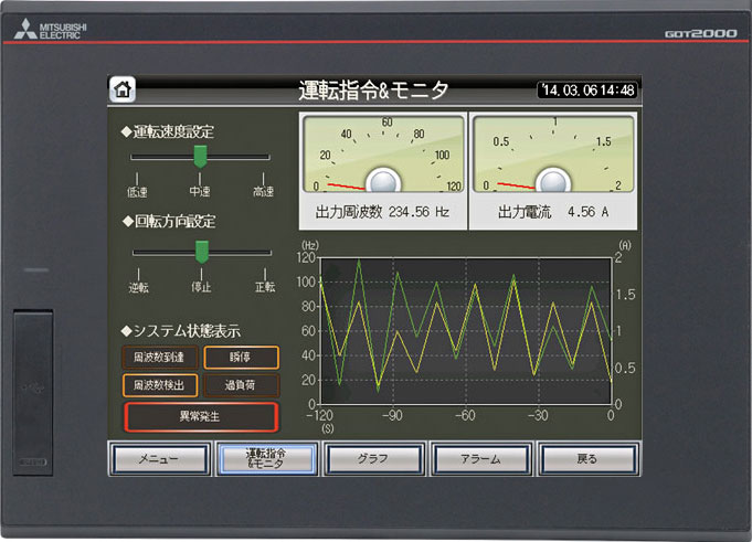
MITSUBISHI GT2510-VTBD Price
- Brand: MITSUBISHI
- Country: JAPAN
- Name: 10.4 inch touch screen
- Model: GT2510-VTBD
- Price: U.S.$ 1377.97
MITSUBISHI GT2510-VTBD
Series Name: F940GOT.
System screen display language: english.
Display: 5.7 inches, suitable for a variety of applications, GOT.
Display color: monochrome.
Display device: LCD STN.
Resolution: 320 * 240.
Installation type: panel mounting.
The built-in communication port: RS-422 (1ch) /RS-232C (1ch).
Power supply voltage: DC24V.
GOT-F900 series can be easily applied to a variety of different applications GT2510-VTBD
3 built-in communication channels.
3 standard communication ports are provided for the same PC (COM2:RS-232C) or a PLC (COM1:RS-232C and COM0:RS-422) communication.
Flexible layout.
F940WGOT can be installed in a vertical or horizontal direction.
The direction of the screen can be directed by programming software.
Screen area.
Through the split screen configuration, you can reduce the operating time.
The image can be divided into two or three parts to display.
According to the user''s application example, the menu screen or the operation of the button sometimes on the screen will often be used to.
As a result, it is very time-consuming and inefficient to make a similar picture every time. Master station module.
DC5V consumption current: 150mA.
Data communication with various machines using Ethernet.
FX3 series through Ethernet expansion device,
The monitoring and maintenance of equipment can be easily carried out in a place far from the scene.
Various machine communication with MODBUS protocol
Special adapter for MODBUS communications,
FX3 series can be used as a master or slave station with a variety of MODBUS protocol machine communication.
High speed counter equipped with 6 to 8 channels.
FX series of all models are standard with a high-speed counter.
Through a simple procedure to achieve high speed control.
Through the CC-Link and a variety of machine communications, the province of wiring.
Using CC-Link to control a variety of FA machines.
FX3G (*) /FX3U (C) series can be expanded by CC-Link control points. Analog channel: 8 channels.
Input / output (resolution): 0 ~ 4000.
Conversion speed: 100ms/8 channel.
Analog module installation.
Power supply: DC24V.
According to the control requirements of the system, using the appropriate design method to design MITSUBISHI PLC program.
Procedures to meet the requirements of system control as the main line,
Write one by one to achieve the control function or the sub task of the program,
Gradually improve the functions specified by the system.
MITSUBISHI PLC detection, fault diagnosis and display and other procedures.
These procedures are relatively independent, generally in the basic completion of the program design and then add.
Hardware simulation method is to use a number of hardware equipment to simulate the generation of the signal,
The signals are connected to the input end of the PLC system in a hard wired way, and the timeliness is strong.
Software simulation method is in the MITSUBISHI PLC in the preparation of a set of simulation program,
The simulation provides the field signal, which is simple and easy to operate, but it is not easy to guarantee the timeliness.
Simulation of the process of debugging, debugging method can be used to segment, and the monitoring function of programmer.
GT2510-VTBD Operation manual/Instructions/Model selection sample download link: /searchDownload.html?Search=GT2510-VTBD&select=5
...more relevant model market price >>>>
Related products
MITSUBISHI
12.1 Inch Touch Screen
GT2512-STBA

Function: high performance and low price
MITSUBISHI
12.1 Inch Touch Screen
GT2512-STBD-GF

Function: high performance and low price
MITSUBISHI
5.7 Inch Touch Screen
GT2705-VTBD

Function: high performance and low price
MITSUBISHI
10.4 inch touch screen
GT2510-VTBA-GF

Function: high performance and low price

