Brand Sort:
MITSUBISHI
MITSUBISHI FX1N-232-BD Price
- Brand: MITSUBISHI
- Country: JAPAN
- Name: RS-232C expansion board
- Model: FX1N-232-BD
- Price: U.S.$ 67.8
MITSUBISHI FX1N-232-BD
Motor: HA-UH type.
Power: 4.5kw.
Speed: 2000r/min.
According to the types of power supply: can be divided into DC motor and AC motor.
The structure and working principle of DC motor can be divided into four parts: brushless DC motor and brushless DC motor.
Brushless DC motor can be divided into: permanent magnet DC motor and DC motor.
DC Motor Division: Series DC motor, DC motor, DC motor and DC motor FX1N-232-BD
Permanent magnet DC Motor Division: rare earth permanent magnet DC motor, ferrite permanent magnet DC motor and aluminum nickel Gu Yongci DC motor. Input and output points: 24 points.
Power supply: DC24V.
Input points: 14 points.
Output points: 10 points.
Output form: relay output.
Power consumption: 21W.
Weight: 0.55KG.
Outline dimension: 90x90x86mm.
FX3GE on the performance of the FX3GA increased analog input / output and Ethernet communication and other built-in features.
Applicable to a wide variety of applications.
Basic unit: 24/40 point.
Third generation standard model.
High flexibility.
Suitable for small scale control of high cost PLC.
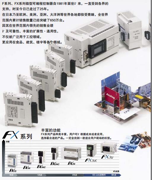
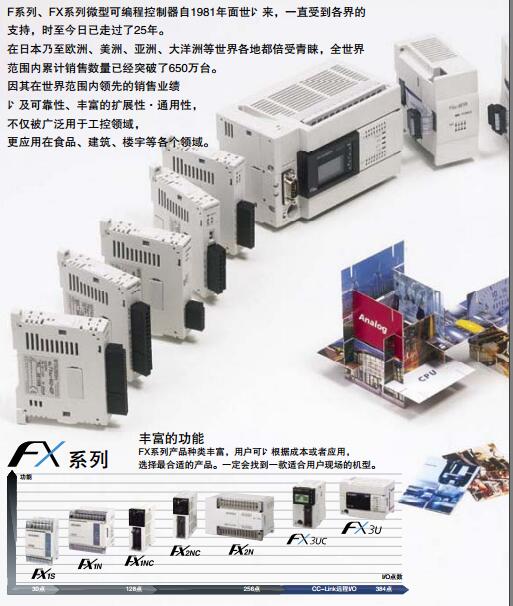
Control points to 128 points, the use of CC-Link remote I/O can control the maximum 256 points.
A versatile PLC.
Built in CPU, power supply, input and output, analog input and output, Ethernet port, can be used immediately after the purchase.
High speed operation.
Basic instructions: 0.21 s/ instruction.
Application instruction: 0.5 s/ instruction.
Large capacity memory.
Built in program memory 32000 steps.
EEPROM memory cartridge with program transfer function. RS-232:1, RS-422/485:1.
Transmission speed: 0.3 ~ 19.2kpbs.
Computer connection function.
A3VCPU special.
Printer / peripheral device connection, BASIC language function.
How to choose MITSUBISHI PLC.
MITSUBISHI PLC options include the choice of MITSUBISHI PLC models, capacity, I/O module, power, etc..
MITSUBISHI PLC distribution I/O points and design MITSUBISHI PLC peripheral hardware circuit
Draw the I/O point of the PLC and the input / output device connection diagram or the corresponding table,
This part also can be carried out in second steps.
Design PLC peripheral hardware circuit.
Draw the electrical wiring diagram of the other parts of the system,
Including the main circuit and the control circuit does not enter the PLC, etc..
The electrical schematic diagram of the system composed of I/O PLC connection diagram and PLC peripheral electrical circuit diagram.
So far the system''s hardware electrical circuit has been determined.
FX1N-232-BD Operation manual/Instructions/Model selection sample download link: /searchDownload.html?Search=FX1N-232-BD&select=5
...more relevant model market price >>>>
Related products
MITSUBISHI
PLC
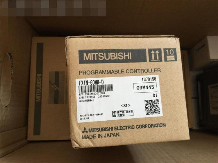
FX1N-60MR-D

Max input / output points: 60 points.
Po
MITSUBISHI
PLC
FX1N-60MR-DS

Max input / output points: 60 points.
Po
MITSUBISHI
RS-422 expansion board
FX1N-422-BD

Function extension oard for RS-422 comm
MITSUBISHI
Analog output expansion board
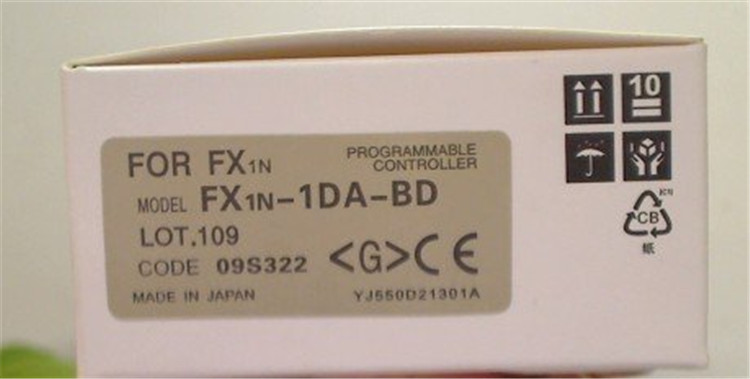
FX1N-1DA-BD

Analog output expansion oard 1 channel

