Brand Sort:
MITSUBISHI
MITSUBISHI FX0S-20MR-001 Price

- Brand: MITSUBISHI
- Country: JAPAN
- Name:
- Model: FX0S-20MR-001
- Price: U.S.$ 405.08
MITSUBISHI FX0S-20MR-001
Output points: 16 points.
Transistor output type. 1 axis servo amplifier.
MITSUBISHI general AC servo amplifier MELSERVO-J4 series.
Rated output: 15.0kw.
Interface: SSCNET III /H.
Power supply: three phase AC400V.
0.6kW and 1kW above the servo amplifier.
Servo amplifier supporting SSCNET III /H.
Complete synchronization system capable of using high speed serial optical communication.
Can be combined with the servo system controller to maximize the performance of the servo system FX0S-20MR-001
The industry''s top level speed motor, the frequency of 2.5kHz amplifier, and optical fiber network extradimensional Symphony orchestra.
Using the traditional two degree of freedom model adaptive control to further optimize the exclusive high speed servo control structure of the dedicated execution engine.
Achieved the fastest 2.5kHz speed frequency response in the industry.
Combined with MITSUBISHI independent research and development of high resolution absolute position encoder (4194304pulses/rev),
Greatly improve the processing speed. Can maximize the performance of high-end machinery. For the GT1665M-VTB.
Applicable model: GT16. 1ch RS-232.
1ch RS-422/485.
Basic language programming module.
The position signal of the first axis servo amplifier, which is used on the motion CPU, is used as a trigger,
Starting from the programmable controller CPU to the second axis servo amplifier,
Time to output speed command of servo amplifier.
This time is the index of data transmission speed between CPU.
Ultra high speed processing, production time is shortened, better performance.
As applications become larger and more complex, it is necessary to shorten the system operation cycle time.
The operation period can be shortened by the super high basic operation speed 1.9ns.
In addition to achieve in the past with the control of single-chip high-speed control,
The system performance can be improved by reducing the total scan time,
To prevent any possible performance bias.
Input and output points: 512 points.
Input / output data points: 512 points.
Program capacity: 14K.
Basic command processing speed (LD command) s:0.20.
Optical data communication line function (GI cable).
Integral type: the PLC components are installed together or a few pieces of printed circuit board,
And together with the power supply installed in the casing to form a single overall called the host or the basic unit, small, ultra small PLC using this structure.
Modular: PLC is the basic components of a separate module.
Medium and large PLC used this way. Easy maintenance.
Each scanning process. Focus on the input signal sampling. Focus on the output signal to refresh.
Input refresh process. When the input port is closed,
Program in the implementation phase, the input end of a new state, the new state can not be read.
Only when the program is scanned, the new state is read.
A scan cycle is divided into the input sample, the program execution, the output refresh.
The contents of the component image register are changed with the change of the execution of the program.
The length of the scan cycle is determined by the three.
CPU the speed of executing instructions.
Time of instruction.
Instruction count.
Due to the adoption of centralized sampling.
Centralized output mode.
There exist input / output hysteresis phenomena, i.e., the input / output response delay.
User program storage capacity: it is a measure of how much the user application can store the number of indicators.
Usually in words or K words as units. 16 bit binary number is a word,
Every 1024 words are 1K words. PLC to store instructions and data in words.
General logical operation instructions each account for 1 words. Timer / counter,
Shift instruction accounted for 2 words. Data operation instructions for 2~4.
FX0S-20MR-001 Operation manual/Instructions/Model selection sample download link: /searchDownload.html?Search=FX0S-20MR-001&select=5
...more relevant model market price >>>>
Related products
MITSUBISHI
PLC
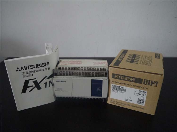
FX1N-40MR-001

Total points: 40 points.
Input points: 2
MITSUBISHI
PLC
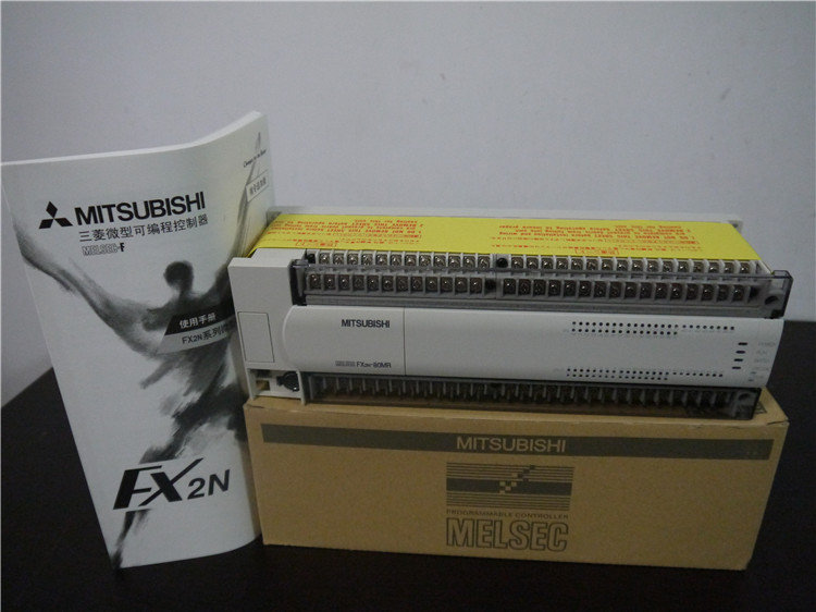
FX2N-80MR-001

Max input / output points: 80 points.
Su
MITSUBISHI
PLC
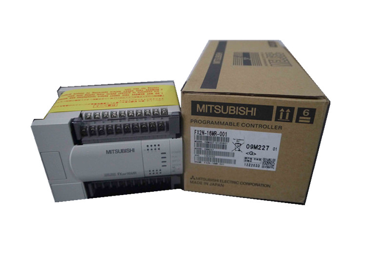
FX2N-16MR-001

Max input / output points: 16 points.
Su
MITSUBISHI
PLC
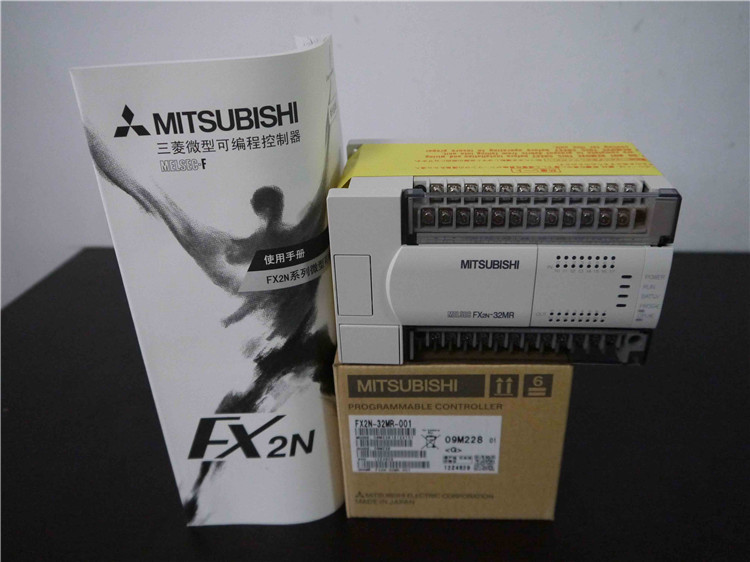
FX2N-32MR-001

Max input / output points: 32 points.
Su
