Brand Sort:
MITSUBISHI
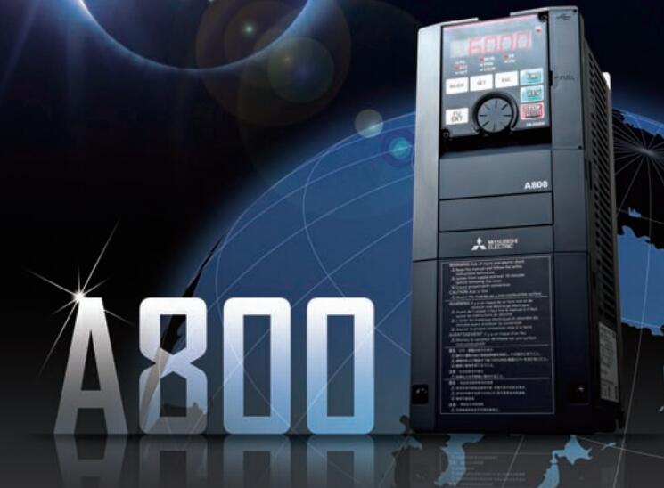
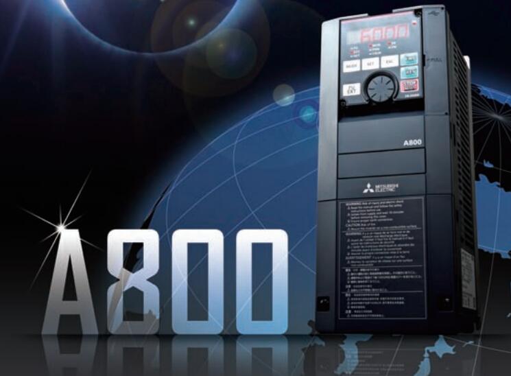
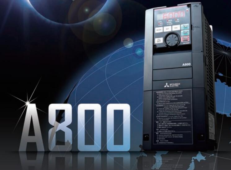
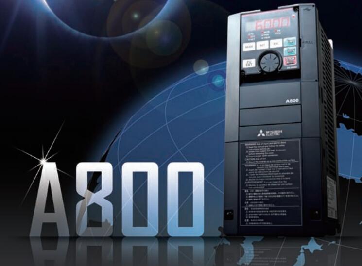
MITSUBISHI FR-A820-01540-2-60 Price

- Brand: MITSUBISHI
- Country: JAPAN
- Name:
- Model: FR-A820-01540-2-60
- Price: U.S.$ 6027.12
MITSUBISHI FR-A820-01540-2-60
Number of channels: 2 channels.
Sensing method and temperature range: PT100.
A1S64TC series component is a kind of temperature controller combined with ANS series CPU.
Components with temperature measurement input and built-in PID algorithm control output, can be used in a variety of temperature control occasions.
Each component controls up to 4 loops at most.
Thermocouple input or PT100 3 wire temperature sensor input FR-A820-01540-2-60
Control output switching signal for the output of the transistor.
BW is a signal with broken line detection function. The terminal row is converted to e-CON.Input points: 16 points.
Input voltage and current: 3/7mA DC12/24V.
Input response time: 10ms.
16 point /1 a public side.
Positive pole sharing.
Output points: 12 points.
Output voltage: DC12V/24V.
OFF leakage current: 0.1mA.
Output response time: 2ms.
Output type: transistor output.
8 point /1 a public end, 4 point /1 a public end.
36 point terminal station.
With the surge absorber.
Control solenoid valve required I/O points by the action principle of the solenoid valve can be known,
A single coil solenoid valve with PLC control to 2 input and 1 output,
A double coil solenoid valve requires 3 inputs and 2 outputs,
A button needs an input; a light sensitive switch needs 4 or 2 inputs,
A signal lamp needs 1 output, band switch,
Several bands are required for several inputs,
In general, a variety of position switches are required to take up 2 input points.
MITSUBISHI PLC is the main product in the production of MITSUBISHI motor in Dalian.
It uses a kind of programmable memory for its internal storage procedures,
Execute logic operation, sequence control, timing, counting and arithmetic operations, user oriented instruction,
And through digital or analog input / output control of various types of machinery or production process.
The number of I/O thyristor DC motor control required tube DC motor speed control system is the main form of DC speed regulation,
The thyristor rectifier unit is used to supply power to the DC motor.
PLC control of the DC drive system, the input of the PLC in addition to the main signal outside the signal,
We need to consider the switching signal, the fault signal transmission device, brake signal and fan fault signal.
The output of the PLC mainly consider the speed command signal positive 1~3 level, 1~3 level, allowing reverse switching signal and brake open signal etc..
In general, a reversible DC drive system controlled by PLC is approximately 12 input points and 8 output points,
An irreversible DC drive system requires 9 inputs and 6 output points.
FR-A820-01540-2-60 Operation manual/Instructions/Model selection sample download link: /searchDownload.html?Search=FR-A820-01540-2-60&select=5
...more relevant model market price >>>>
Related products
MITSUBISHI
Three phase 200V grade frequency converter
FR-A820-0.4K-1(FR-A820-00046-2-60)

MITSUBISHI inverter series: FR-A820.
Vol
MITSUBISHI
Three phase 200V grade frequency converter
FR-A820-2.2K-1(FR-A820-00167-2-60)

MITSUBISHI inverter series: FR-A820.
Vol
MITSUBISHI
Three phase 200V grade frequency converter
FR-A820-3.7K-1(FR-A820-00250-2-60)

MITSUBISHI inverter series: FR-A820.
Vol
MITSUBISHI
Three phase 200V grade frequency converter
FR-A820-11K-1(FR-A820-00630-2-60)

MITSUBISHI inverter series: FR-A820.
Vol
