Brand Sort:
MITSUBISHI
MITSUBISHI AD75P2-S3 Price
- Brand: MITSUBISHI
- Country: JAPAN
- Name: Positioning module
- Model: AD75P2-S3
- Price: U.S.$ 2032.2
MITSUBISHI AD75P2-S3
MITSUBISHI inverter FR-F740 series.
Voltage level: three phase 400V.
Frequency converter capacity: 400KW.
The main circuit of the inverter can be divided into two categories in general: voltage type is the voltage source of the DC converter for AC inverter,
The filtering of the DC circuit is the capacitance; the current mode is the DC conversion of the current source to the AC inverter,
The DC loop filter is the inductor AD75P2-S3
Why is the frequency of the inverter voltage proportional to the change?
The electromagnetic torque of any motor is the result of the interaction between the current and the magnetic flux, the current is not allowed to exceed the rated value, otherwise it will cause the heating of the motor.
Therefore, if the magnetic flux decreases, the electromagnetic torque will decrease, which leads to the reduction of the load carrying capacity. Cable length 1.2 meters.
Extended substrate for connection.Cable length: 5.0m.
For the connection between QnAS/AnSCPU/ motion controller GOT (A Series) and CPU.
Applicable models: GT16, GT15, GT11. Memory format: flash memory.
Number of steps: up to 16000 steps.
Battery support: do not.
Write, delete method: installed on the PLC through the peripheral devices to write, delete. MELSECNET/10, MELSECNET/H coaxial.
Input voltage: AC100-240V.
How to choose MITSUBISHI PLC.
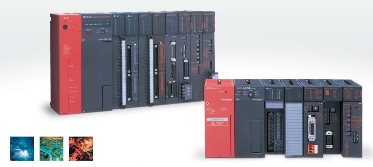
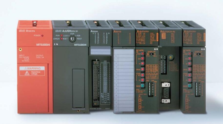
MITSUBISHI PLC options include the choice of MITSUBISHI PLC models, capacity, I/O module, power, etc..
MITSUBISHI PLC distribution I/O points and design MITSUBISHI PLC peripheral hardware circuit
Draw the I/O point of the PLC and the input / output device connection diagram or the corresponding table,
This part also can be carried out in second steps.
Design PLC peripheral hardware circuit.
Draw the electrical wiring diagram of the other parts of the system,
Including the main circuit and the control circuit does not enter the PLC, etc..
The electrical schematic diagram of the system composed of I/O PLC connection diagram and PLC peripheral electrical circuit diagram.
So far the system''s hardware electrical circuit has been determined.
AD75P2-S3 Operation manual/Instructions/Model selection sample download link: /searchDownload.html?Search=AD75P2-S3&select=5
...more relevant model market price >>>>
Related products
MITSUBISHI
Positioning module
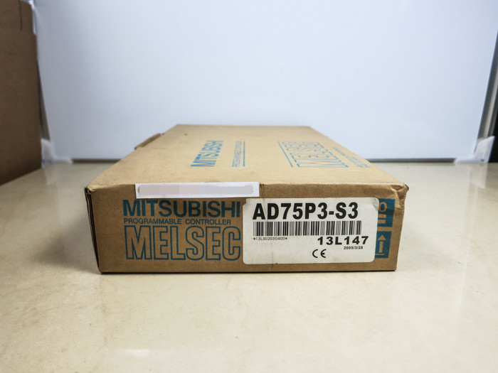
AD75P3-S3

3 axes.
2 axis linear interpolation, 2 a
MITSUBISHI
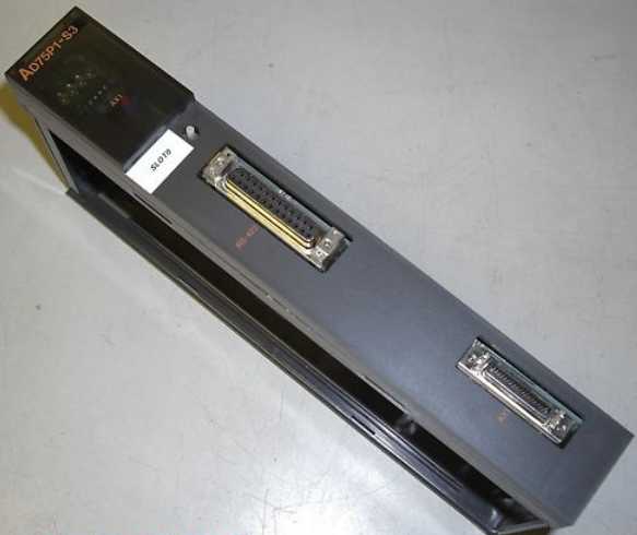
Positioning module
AD75P1-S3

1 axes.
2 axis linear interpolation, 2 a
MITSUBISHI
Positioning module
AD75M2

2 axes.
2 axis linear interpolation, 2 a
MITSUBISHI
Modular
A1SJ71B62-S3

Signal transmission device B/NET interfa

