Brand Sort:
MITSUBISHI
MITSUBISHI A68B Price
- Brand: MITSUBISHI
- Country: JAPAN
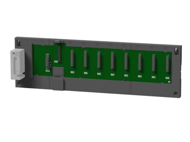
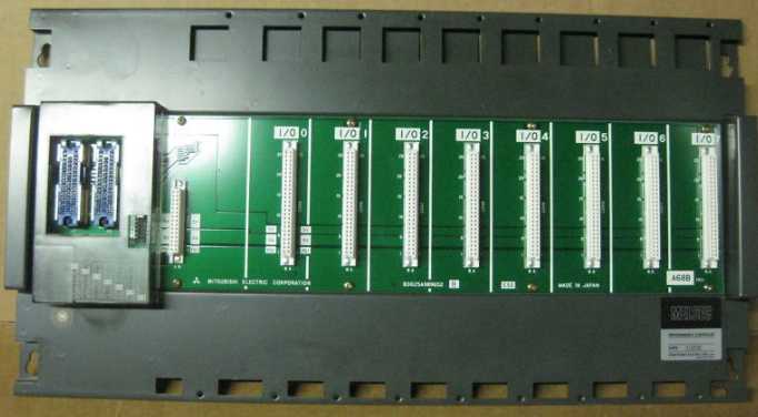
- Name: Extended bottom plate
- Model: A68B
- Price: U.S.$ 754.24
MITSUBISHI A68B
Power: 0.75kw.
Purpose: high frequency braking resistor.
The use rate of the built-in regenerative brake of the transducer can be promoted.
When using the FR-ABR type brake resistor, the short circuit piece between the terminal PR-PX is removed. Does not remove the short circuit chip will lead to overheating of the brake resistor.
The utilization rate of the regenerative braking should be less than the allowable brake use rate in the above table A68B
With the operating frequency of the brake resistor to reach 300 degrees C or higher, it is necessary to take protective measures and cooling.
MYS type resistor can be used. But please pay attention to the allowable brake use rate.
Do not remove the terminal P/+ and P1 between the short circuit chip, in addition to connecting the DC reactor.
The installation of thermal relay, to avoid overheating and burn the braking resistor. Output type: transistor output, drain type.
Output points: 8 points.
OFF leakage current: 0.1mA.
Output protection function.
Rated load voltage / current: DC24V/0.1A.
External connection: 2 wire.
Sensor connection type.
Minimum size of industry.
When installing the module can choose to use the DIN guide rail or screw mounting.
3 wire sensor input. Screw, 2 piece type terminal
Platinum temperature measuring resistor body PT100 temperature input module.
Number of channels: 4 channels.
Number of stations: 4 stops.
Station type: remote equipment station.
MITSUBISHI PLC online debugging.
On-line debugging is the process that will through the simulation debugging to further carry on the on-line unification to adjust.
On-line debugging process should be step by step,
From MITSUBISHI PLC only connected to the input device, and then connect the output device, and then connect to the actual load and so on and so on step by step.
If you do not meet the requirements, the hardware and procedures for adjustment.
Usually only need to modify the part of the program can be.
MITSUBISHI PLC hardware implementation
Hardware implementation is mainly for the control cabinet and other hardware design and field construction.
Design control cabinet and the operating table and other parts of the electrical wiring diagram and wiring diagram.
Electrical interconnection diagram of each part of the design system.
According to the construction drawings of the site wiring, and carry out a detailed inspection.
Because the program design and hardware implementation can be carried out at the same time,
So the design cycle of the MITSUBISHI PLC control system can be greatly reduced.
A68B Operation manual/Instructions/Model selection sample download link: /searchDownload.html?Search=A68B&select=5
...more relevant model market price >>>>
Related products
MITSUBISHI
Old small A series main substrate
QA1S38B

8 slots requires 1 AnS series PLC power
MITSUBISHI
Connector / terminal conversion module
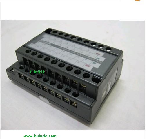
A6TBXY36

For common cathode input module and drai
MITSUBISHI
Temperature input module
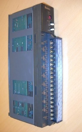
A68RD3N

8 channels.
3 wire platinum measuring an
MITSUBISHI
Interface unit of ultrasonic linear meter
A64BTL

4 channels.
Measurement range: 0.000-355

