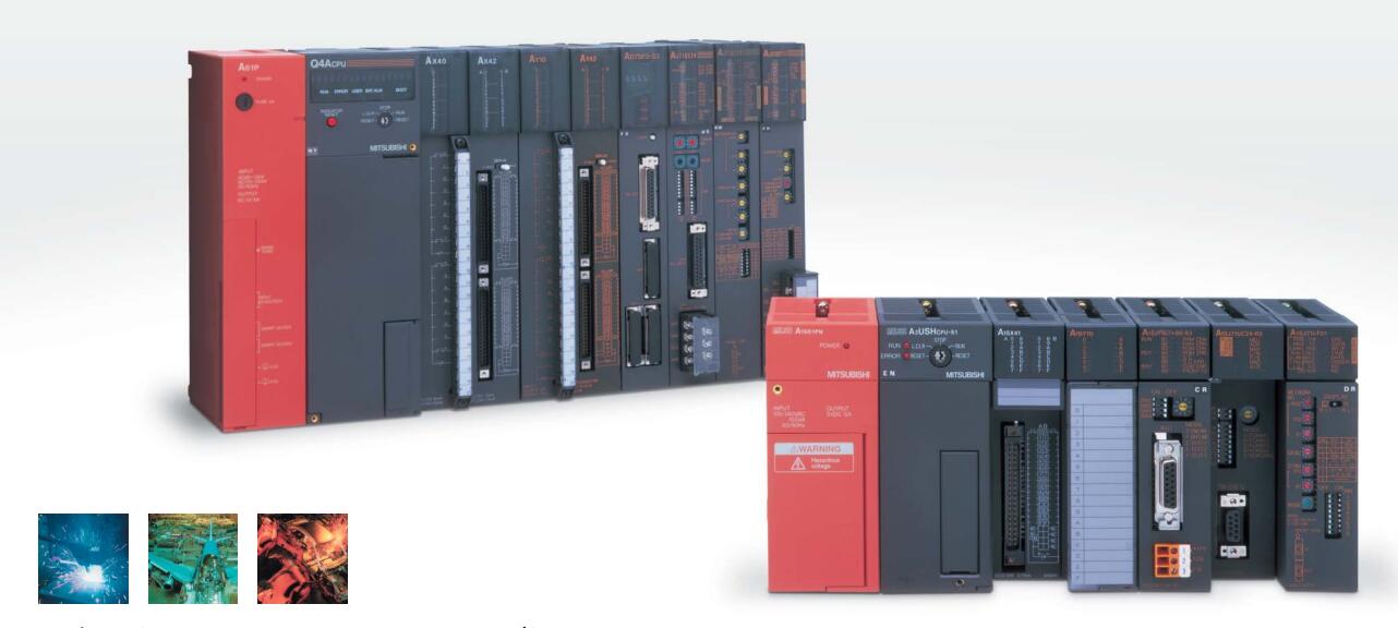
Brand Sort:
MITSUBISHI
MITSUBISHI A2NCPUP21-S3 Price
- Brand: MITSUBISHI
- Country: JAPAN
- Name: CPU unit
- Model: A2NCPUP21-S3
- Price: 0 >
MITSUBISHI A2NCPUP21-S3
CC-Link/LT master station.
Transmission speed: 2.5Mbps.
Remote input / output: 1024 points.
16 point mode.
In the cabinet, the device can also respond to high speed.
CC-Link/LT link scan time to reach the highest 1.2ms (2.5Mbps) at 64 stations,
Excellent response performance is achieved.
Can be selected according to the transmission distance 2.5Mbps, 625kbps, 156kbps.
Comfortable environment without network awareness A2NCPUP21-S3
Parameter settings that do not require any trouble.
Moreover, the transmission speed only through the master module to set, can easily use the remote I/O. 3C-2V/5C-2V coaxial cable between the single bus PC network (control station / common station) / remote I/O network (remote master).
Q mode.
When the programmer input programinto the user program memory,
Then CPU according to the function of the system (the system program memory to explain the compiler),
Translate the user program into PLC internally recognized by the user to compile the program.
Input status and input information input from the input interface,
CPU will be stored in the working data memory or in the input image register.
And then combine the data and the program with CPU.
The result is stored in the output image register or the working data memory,
And then output to the output interface, control the external drive.
Semiconductor circuit with memory function.
System program memory and user memory.
System program memory for storing system program,
Including management procedures, monitoring procedures, as well as the user program to do the compiler to compile the process of interpretation.
Read only memory. Manufacturers use, content can not be changed, power does not disappear.
User memory: user program storage area and work data storage area.
Composed of random access memory (RAM). User use.
Power cut off. Commonly used efficient lithium battery as a backup power supply, life is generally 3~5 years. Remote I/O controller, coaxial cable, coaxial loop system.
How to choose MITSUBISHI PLC.
MITSUBISHI PLC options include the choice of MITSUBISHI PLC models, capacity, I/O module, power, etc..
MITSUBISHI PLC distribution I/O points and design MITSUBISHI PLC peripheral hardware circuit
Draw the I/O point of the PLC and the input / output device connection diagram or the corresponding table,
This part also can be carried out in second steps.
Design PLC peripheral hardware circuit.
Draw the electrical wiring diagram of the other parts of the system,
Including the main circuit and the control circuit does not enter the PLC, etc..
The electrical schematic diagram of the system composed of I/O PLC connection diagram and PLC peripheral electrical circuit diagram.
So far the system''s hardware electrical circuit has been determined.
A2NCPUP21-S3 Operation manual/Instructions/Model selection sample download link: /searchDownload.html?Search=A2NCPUP21-S3&select=5
...more relevant model market price >>>>
Related products
MITSUBISHI
CPU unit
A2NCPU-S1
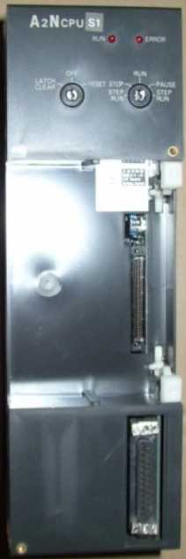
Input and output points: 1024 points.
In
MITSUBISHI
CPU unit
A2NCPU
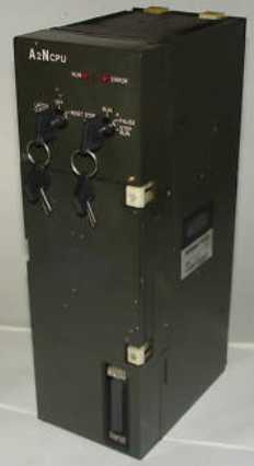
Input and output points: 512 points.
Inp
MITSUBISHI
CPU unit
A2NCPUP21-S4
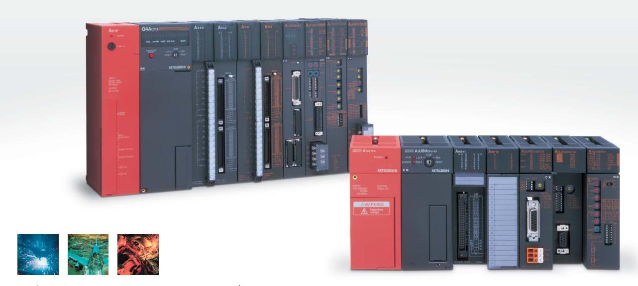
Input and output points: 1024 points.
In
MITSUBISHI
CPU unit
A2NCPUP21-S1
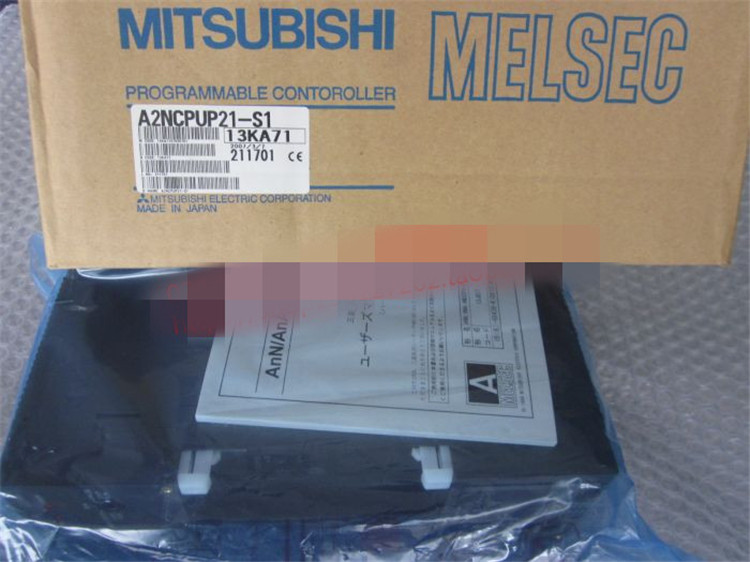
Input and output points: 1024 points.
In

