Brand Sort:
MITSUBISHI
MITSUBISHI A1SY50 Price
- Brand: MITSUBISHI
- Country: JAPAN
- Name: Transistor leakage type output module
- Model: A1SY50
- Price: U.S.$ 264.41
MITSUBISHI A1SY50
Cable flat cable;
Connector with 20 pin installed at both ends of the fuse.
Length 3M. Power: 55kw.
Purpose: to suppress the power harmonics.
Connected to the inverter input, can be used to improve the power factor, reduce the input side of the high harmonic current.
According to the motor power used to select AC reactor.
(when the inverter capacity is greater than the motor capacity, is still based on the motor capacity to choose A1SY50) Capacity: 8M bytes.
Support SD memory card.
High speed universal QCPU support SD memory card,
In order to be able to have a memory card port between SD and PC to easily realize data exchange.
In addition, the SD memory card and the extended SRAM card can be used simultaneously.
Therefore, the extension of the file register using the extended SRAM card,
SD memory card can be used at the same time to carry out the data file record, a large number of annotation data storage, through the memory card to guide operation.
Better user experience data recording function.
Easy to record, no need to program.
Simply through the special configuration tool wizard to easily complete the settings,
The collected data can be saved in CSV format to SD storage card.
Can be effectively used to save the CSV file to facilitate the creation of a variety of reference materials,
Including daily reports, generate reports and general reports.
These data can be applied to the data analysis, tracing, etc..
Simply insert the SD memory card, you can automatically record.
Simply insert the SD in the CPU to save the record setting file, you can automatically start recording.
Even when remote data collection is required,
After receiving a record setting file by mail and copy it to the SD memory card,
Can immediately start recording.DC input points: 16 points.
Input voltage and current: 5mA, DC24V.
Response time: 10ms.
16 point /1 a public side.
Positive / negative sharing.
Output points: 16 points.
Output voltage and current: DC24V, 0.1A/1 point, 1.6A/1 common end.
Response time: 2ms.
16 point /1 a public side.
Output form: transistor output, leakage type.
40 pin connector.
Number of stations: 4 stops.
According to the control requirements of the system, using the appropriate design method to design MITSUBISHI PLC program.
Procedures to meet the requirements of system control as the main line,
Write one by one to achieve the control function or the sub task of the program,
Gradually improve the functions specified by the system.
MITSUBISHI PLC detection, fault diagnosis and display and other procedures.
These procedures are relatively independent, generally in the basic completion of the program design and then add.
Hardware simulation method is to use a number of hardware equipment to simulate the generation of the signal,
The signals are connected to the input end of the PLC system in a hard wired way, and the timeliness is strong.
Software simulation method is in the MITSUBISHI PLC in the preparation of a set of simulation program,
The simulation provides the field signal, which is simple and easy to operate, but it is not easy to guarantee the timeliness.
Simulation of the process of debugging, debugging method can be used to segment, and the monitoring function of programmer.
A1SY50 Operation manual/Instructions/Model selection sample download link: /searchDownload.html?Search=A1SY50&select=5
...more relevant model market price >>>>
Related products
MITSUBISHI
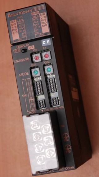
Serial communication module
A1SJ71QC24N

RS-232 1 channel.
RS-422/485 1 channel.
MITSUBISHI
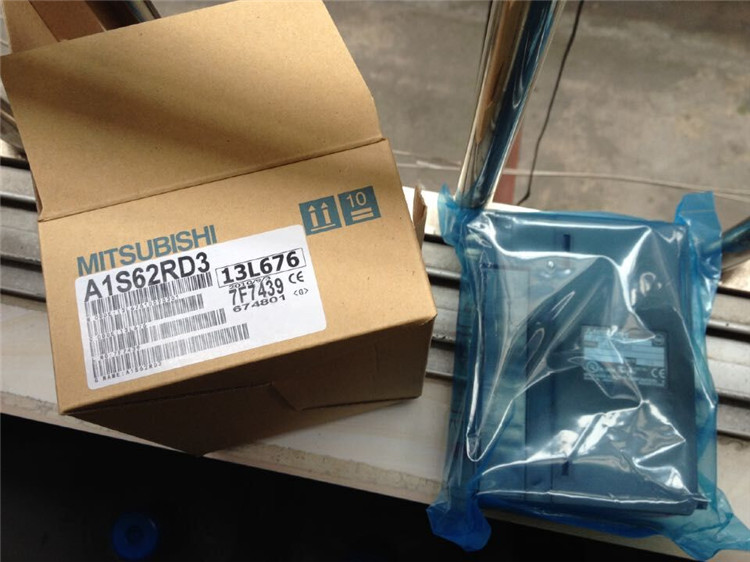
Temperature sensor input module
A1S62RD3

Temperature sensor: PT100, 3 wire system
MITSUBISHI
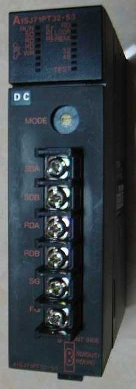
Master control module
A1SJ71PT32-S3

Cale type: cale or twisted pair.
A1SJ7
MITSUBISHI
I/O bus monitoring module
A1SS91

A1SS91 is used to insert a fixed control

