Brand Sort:
MITSUBISHI
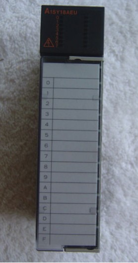
MITSUBISHI A1SY18AEU Price
- Brand: MITSUBISHI
- Country: JAPAN
- Name: Relay output module
- Model: A1SY18AEU
- Price: U.S.$ 335.59
MITSUBISHI A1SY18AEU
Motor series: low inertia, medium and small capacity.
Using a serial absolute / incremental encoder.
Rated output power: 0.75kw.
Rated speed: 3000rpm.
With a brake band.
Shaft end: straight shaft.
Comparison of single phase induction motor and servo motor.
The working principle of the AC servo motor is similar to that of the single phase induction motor,
But the rotor resistance of the former is much larger than that of the latter,
So the servo motor is compared with the single machine asynchronous motor,
There are three notable features:
1, large starting torque A1SY18AEU
2, a wide range of operation.
3, no rotation phenomenon.
AC servo motor running smoothly, low noise.
But the control characteristic is non-linear, and because the rotor resistance is big, the loss is big, the efficiency is low,
Therefore, compared with the same capacity DC servo motor, the volume is large and the weight is heavy,
So it is only suitable for 0.5-100W small power control system. Cable length: 1.2m.
For the connection between QnAS/AnSCPU/ motion controller GOT (A Series) and CPU.
Applicable models: GT16, GT15, GT11. Number of channels: 4 channels.
Sensing method and temperature range: PT100.
A1S64TC series component is a kind of temperature controller combined with ANS series CPU.
Components with temperature measurement input and built-in PID algorithm control output, can be used in a variety of temperature control occasions.
Each component controls up to 4 loops at most.
Thermocouple input or PT100 3 wire temperature sensor input.
Control output switching signal for the output of the transistor.
BW is a signal with broken line detection function. Input and output points: 1024 points.
Input / output data points: 1024 points.
Program capacity: 14K.
Basic command processing speed (LD command) s:0.20.
Optical data communication line.
Each scanning process. Focus on the input signal sampling. Focus on the output signal to refresh.
Input refresh process. When the input port is closed,
Program in the implementation phase, the input end of a new state, the new state can not be read.
Only when the program is scanned, the new state is read.
A scan cycle is divided into the input sample, the program execution, the output refresh.
The contents of the component image register are changed with the change of the execution of the program.
The length of the scan cycle is determined by the three.
CPU the speed of executing instructions.
Time of instruction.
Instruction count.
Due to the adoption of centralized sampling.
Centralized output mode.
There exist input / output hysteresis phenomena, i.e., the input / output response delay.
User program storage capacity: it is a measure of how much the user application can store the number of indicators.
Usually in words or K words as units. 16 bit binary number is a word,
Every 1024 words are 1K words. PLC to store instructions and data in words.
General logical operation instructions each account for 1 words. Timer / counter,
Shift instruction accounted for 2 words. Data operation instructions for 2~4.
A1SY18AEU Operation manual/Instructions/Model selection sample download link: /searchDownload.html?Search=A1SY18AEU&select=5
...more relevant model market price >>>>
Related products
MITSUBISHI
output module
A1SY10EU

Output type: relay.
Output points: 16 po
MITSUBISHI
output module
A1SY10

Output type: relay.
Output points: 16 po
MITSUBISHI
output module
A1SY81

Output type: transistor source.
Output p


