Brand Sort:
MITSUBISHI
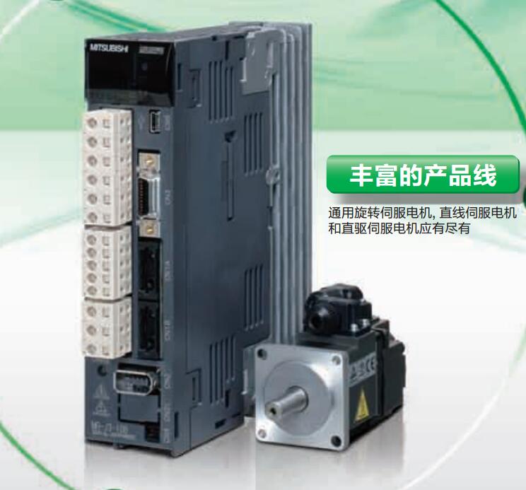
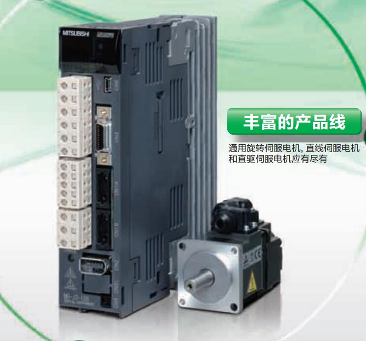
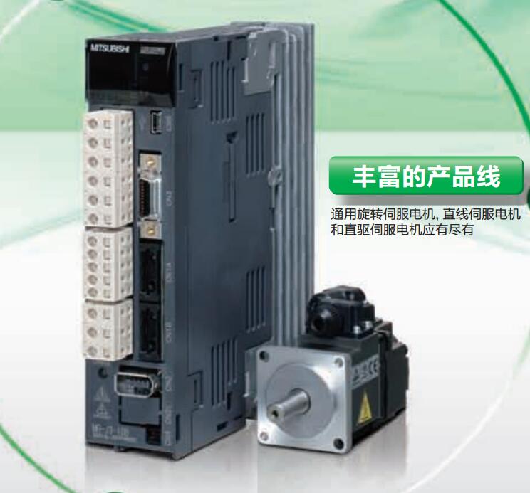
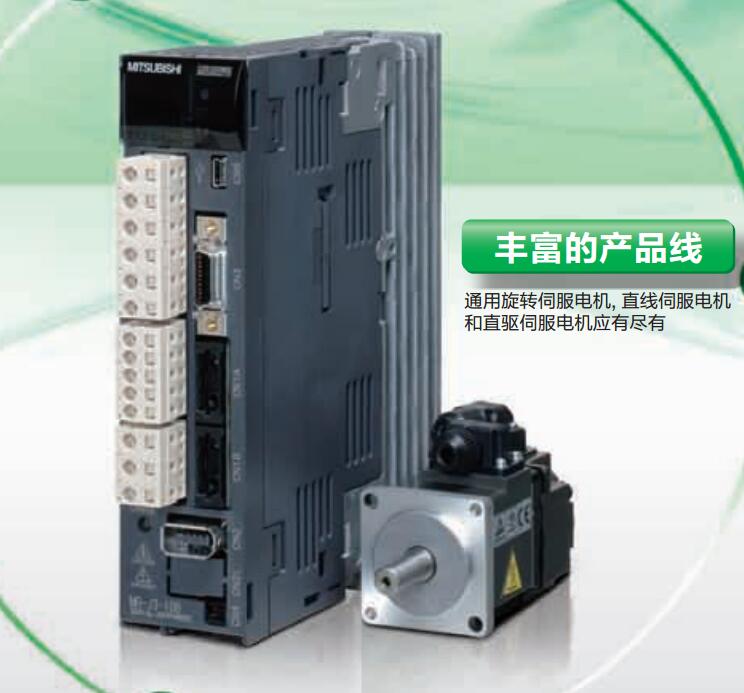
MITSUBISHI MR-J3-700B4-RJ006 Price
- Brand: MITSUBISHI
- Country: JAPAN
- Name: Full closed loop control driver
- Model: MR-J3-700B4-RJ006
- Price: 0 >
MITSUBISHI MR-J3-700B4-RJ006
Protective film for 8.4 inch screen.
Transparent (frame: white), 5.
Applicable model: GT15. Application: save sampled data, alarm frequency, and alarm records.
The image data is stored in a built-in flash memory and can be maintained even at the end of the battery life.
Life expectancy is about 5 years.
Specifications: 850mA 3.6V.
Application Series: F940WGOT, F940GOT. Max input / output points: 20 points MR-J3-700B4-RJ006
Supply voltage: 100 - 240VAC.
Input points: 12 points.
Output points: 8 points.
Output type: Transistor (source).
Power consumption (W): 7.
Weight (kg):0.3.
Size (WxHxD) mm:75x90x75.
Host has 10 points (6I/4O), 14 points (8I/6O), 20 points (12I/8O), 30 points (16I/14O) of 4 types.
This type of PLC is mainly used in all of the digital input, digital output control point of the device.
Can be directly connected to the 220V city power, built-in 8K step EEPROM memory, no battery, easy to maintain.
The series transistor output (MT) of the PLC, can be output 2 100KHz pulse, direct drive servo or stepper motor.
The series PLC can not be brought with the expansion module, but can be installed by the BD board to extend a small amount of I/O.
The series 1N through the installation of BD series PLC board, can achieve RS232, RS485, RS422 communication. MELSECNET/MINI (-S3) data link system, A2C system transfer converter.
Twisted pair cable -GI optical fiber cable.
MITSUBISHI PLC protection and chain procedures.
Protection and chain is an indispensable part of the program, must be carefully considered.
It can avoid the control logic confusion caused by illegal operations.
MITSUBISHI PLC initialization procedure. After MITSUBISHI PLC on power, the general need to do some of the initial operation,
In order to start making necessary preparations, to avoid the wrong operation of the system.
The main contents of the initialization program are: to some data area, counter and so on,
Data needed to restore some of the data area,
Set or reset some relays,
For some initial state display, etc..
MITSUBISHI PLC program simulation debugging
The basic idea of program simulation debugging is,
In order to facilitate the form of simulation to generate the actual state of the scene,
Create the necessary environmental conditions for the operation of the program.
Depending on the way the field signals are generated,
The simulation debugging has two forms of hardware simulation and software simulation.
MR-J3-700B4-RJ006 Operation manual/Instructions/Model selection sample download link: /searchDownload.html?Search=MR-J3-700B4-RJ006&select=5
...more relevant model market price >>>>
Related products
MITSUBISHI
Suitable for linear servo motor drive
MR-J3-700B-RJ004

MITSUBISHI motor universal AC servo ampl
MITSUBISHI
Full closed loop control driver
MR-J3-350B4-RJ006

MITSUBISHI motor universal AC servo ampl
MITSUBISHI
Full closed loop control driver
MR-J3-100B4-RJ006

MITSUBISHI motor universal AC servo ampl
MITSUBISHI
Integrated drive safety function driver
MR-J3-700BS

MITSUBISHI motor universal AC servo ampl

