Brand Sort:
MITSUBISHI
MITSUBISHI HF-JP15K1M4 Price
- Brand: MITSUBISHI
- Country: JAPAN
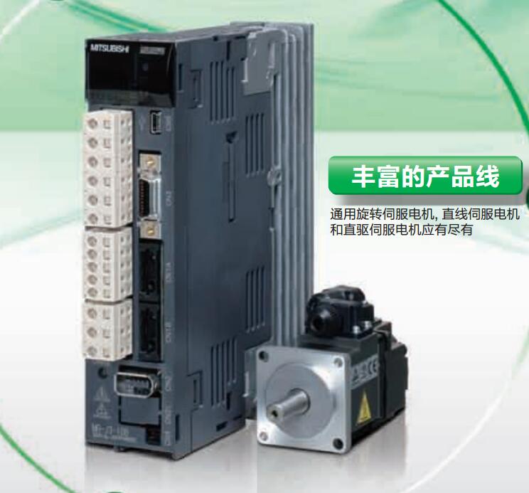
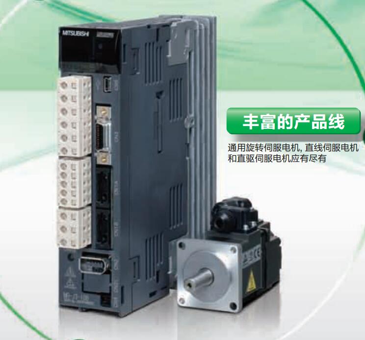
- Name: Low inertia medium / high power servo motor
- Model: HF-JP15K1M4
- Price: 0 >
MITSUBISHI HF-JP15K1M4
G1-50/125 fiber optic cable.
Double loop.
PC inter network (management station / station) / remote I/O network (remote control station).
How to choose MITSUBISHI PLC.
MITSUBISHI PLC options include the choice of MITSUBISHI PLC models, capacity, I/O module, power, etc..
MITSUBISHI PLC distribution I/O points and design MITSUBISHI PLC peripheral hardware circuit
Draw the I/O point of the PLC and the input / output device connection diagram or the corresponding table,
This part also can be carried out in second steps HF-JP15K1M4
Design PLC peripheral hardware circuit.
Draw the electrical wiring diagram of the other parts of the system,
Including the main circuit and the control circuit does not enter the PLC, etc..
The electrical schematic diagram of the system composed of I/O PLC connection diagram and PLC peripheral electrical circuit diagram.
So far the system''s hardware electrical circuit has been determined. Servo motor series: low inertia, medium power.
Rated output: 0.5kw.
Rated speed: 2000r/min.
Electromagnetic brake: with.
Shaft end specification: Standard (straight axis).
Features: low inertia is widely used in general machinery.
IP level: IP65.
Application example:
1, roller type feeding equipment.
2, loading / unloading equipment.
3, high frequency transmission system.
Abundant motor product line can optimize the performance of the machine.
Has a rich motor product line including a rotary servo motor, linear servo motor and direct drive motor. Type of input: DC source.
Input points: 32 points.
Input voltage: 5/12.
Input current: 1.2/3.3mA.
Connection mode: terminal row.
Common common point: 32.
Functional block diagram language is a kind of PLC programming language, which is similar to digital logic circuit.
The function module is used to represent the function of the module,
Different function modules have different functions.
Functional module figure programming language features: functional block diagram programming language is characterized by a functional module for the unit,
Analysis and understanding of the control scheme is simple and easy: function module is to use graphical form of expression,
Intuitive, for a digital logic circuit based on the design of the staff is very easy to master the programming;
Control system with complex scale and complex control logic,
Because the function module diagram can clearly express the function relation, the programming debugging time is greatly reduced.
HF-JP15K1M4 Operation manual/Instructions/Model selection sample download link: /searchDownload.html?Search=HF-JP15K1M4&select=5
...more relevant model market price >>>>
Related products
MITSUBISHI
Low inertia medium / high power servo motor
HF-JP15K1M4B

Servo motor series: low inertia, medium
MITSUBISHI
Low inertia medium / high power servo motor
HF-JP7034

Servo motor series: low inertia, medium
MITSUBISHI
Low inertia medium / high power servo motor
HF-JP503B

Servo motor series: low inertia, medium
MITSUBISHI
Low inertia medium / high power servo motor
HF-JP15K1M4

Servo motor series: low inertia, medium
