Brand Sort:
MITSUBISHI
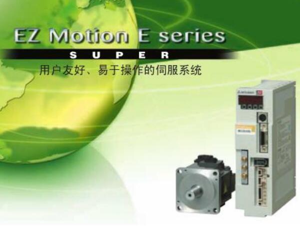
MITSUBISHI HA-SH202B Price
- Brand: MITSUBISHI
- Country: JAPAN
- Name: servo motor
- Model: HA-SH202B
- Price: 0 >
MITSUBISHI HA-SH202B
Data format: RTU.
Data bits: 8.
A1SJ71UC24-R2-S2 and A1SJ71UC24-R4-S2 allow the Ans series PLC to be connected to the MODBUS network,
As the network from the station, and in accordance with the instructions of the main station of the CPU Ans user storage area for data reading / writing.
In addition to supporting the MODBUS protocol, these components also support the standard dedicated communication protocol for A1SJ71UC24 components HA-SH202B
This feature makes the main station of the data acquisition and control with more flexibility.
Support MODBUS slave station protocol.
Supports 1 to 21 function code.
Two transmission modes: RTU or ASCII. The telephone line of the interface module is connected with the peripheral equipment.Cable length: 3 meters.
For FXCPU (FX0, FX0S, FX0N, FX1S, FX1N, FX2N, FX2NC,) and GOT connection.
For FXCPU expansion board FX2N-422-B, FX1N-422-BD and GOT connection. Output type: transistor output, drain type.
Output points: 16 points.
OFF leakage current: 0.25mA.
Output protection function.
Rated load voltage / current: DC12V/DC24V/0.5A.
External connection: 1 wire.
According to the external connection mode and the external equipment input and output specifications,
Choose from a rich product lineup.
Finger protection through the upper part of the terminal,
The human body will not be exposed to live parts,
Therefore, the terminal station type remote I/O module can be directly mounted to the machine tool. Power: 37kw.
Voltage: 200V.
There are 100% braking torque output in continuous regeneration, which can correspond to the continuous regeneration operation of the pipeline control.
There is no need to install the braking unit for each frequency converter, which can reduce the comprehensive space and reduce the comprehensive cost.
Renewable energy can be used for other frequency converter, excess energy back to the grid, to achieve energy saving. 3C-2V/5C-2V coaxial cable.
Single bus.
PC inter network (management station / station) / remote I/O network (remote control station).
How to choose MITSUBISHI PLC.
MITSUBISHI PLC options include the choice of MITSUBISHI PLC models, capacity, I/O module, power, etc..
MITSUBISHI PLC distribution I/O points and design MITSUBISHI PLC peripheral hardware circuit
Draw the I/O point of the PLC and the input / output device connection diagram or the corresponding table,
This part also can be carried out in second steps.
Design PLC peripheral hardware circuit.
Draw the electrical wiring diagram of the other parts of the system,
Including the main circuit and the control circuit does not enter the PLC, etc..
The electrical schematic diagram of the system composed of I/O PLC connection diagram and PLC peripheral electrical circuit diagram.
So far the system''s hardware electrical circuit has been determined.
HA-SH202B Operation manual/Instructions/Model selection sample download link: /searchDownload.html?Search=HA-SH202B&select=5
...more relevant model market price >>>>
Related products
MITSUBISHI
servo motor
HA-SH121B
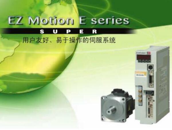
Type: HA-SH series.
Rated output: 1.2KW.
MITSUBISHI
servo motor
HA-SE81B
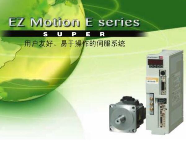
Type: HA-SE series.
Rated output: 0.85KW
MITSUBISHI
servo motor
HA-SE202B
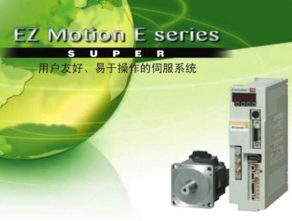
Type: HA-SE series.
Rated output: 2.0KW.
MITSUBISHI
servo motor
HA-SH152B
Type: HA-SH series.
Rated output: 1.5KW.

