Brand Sort:
MITSUBISHI
MITSUBISHI HA-LP11K2 Price
- Brand: MITSUBISHI
- Country: JAPAN
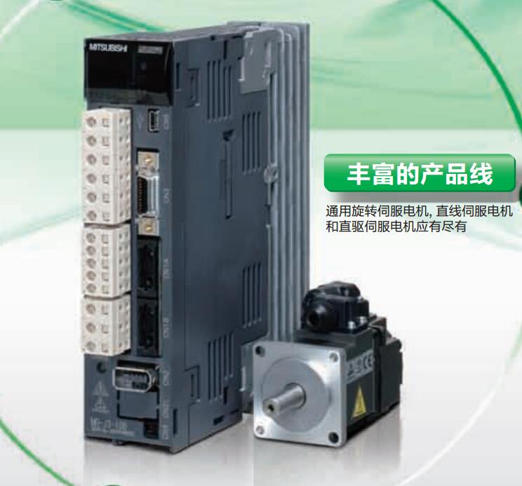
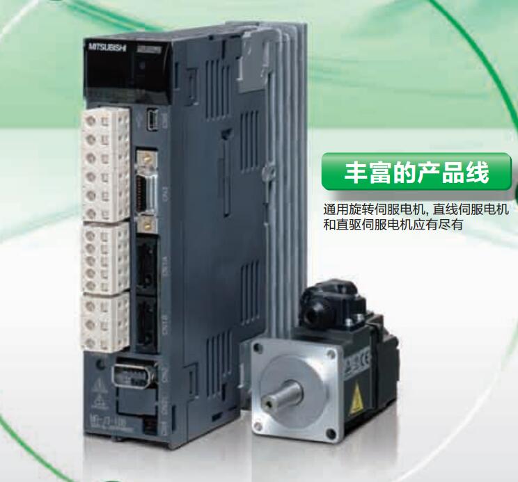
- Name: Low inertia medium / high power servo motor
- Model: HA-LP11K2
- Price: 0 >
MITSUBISHI HA-LP11K2
MITSUBISHI inverter series: FR-A820.
Voltage level: three phase 200V.
Power: 55kw.
SLD converter rated current: 316A.
Structure and function: Standard model.
Type: CA.
Substrate coating: have.
Parameters can be selected by 4 different rated current and different overload rating (SLD (ultra light load) rated, LD (light load) rating, ND (general load) rating, HD (weight).
Type load) for selection.
You can choose the most suitable frequency converter for use; and by selecting a transducer with a SLD or LD rated level,
Be able to reduce the size of the device (compared with the FR-A700 series, to reduce the volume of equipment) HA-LP11K2
For applications that require high torque at low speeds, the HD rating is the most suitable.
The controller is used to control and monitor the frequency converter through the network.
Standard corresponding RS-485 communication (MITSUBISHI converter protocol, Modbus-RTU protocol) data transmission speed up to 115200bps. Length: 2m.
Specification: MR-C. Motor series: medium inertia, medium power.
Rated output power: 3.5kw.
Rated speed: 2000r/min.
Whether to take the brake: No.
Shaft keyway: (open slot).
Protection level: IP65 (IP67).
Features: medium inertia from low speed to high speed three modes for selection, suitable for different applications.
Application examples: transmission machinery, robots, X-Y working platform.
High resolution encoder 131072p/rev (17 bit).
The encoder with high resolution ensures excellent performance and stability at low speed.
All motor dimensions are the same as before and all are compatible with the wiring.
RS-232:1, RS-422/485:1.
Transmission speed: 0.3 ~ 19.2kpbs.
Computer connection function.
A3VCPU special.
Printer / peripheral device connection, BASIC language function.
How to choose MITSUBISHI PLC.
MITSUBISHI PLC options include the choice of MITSUBISHI PLC models, capacity, I/O module, power, etc..
MITSUBISHI PLC distribution I/O points and design MITSUBISHI PLC peripheral hardware circuit
Draw the I/O point of the PLC and the input / output device connection diagram or the corresponding table,
This part also can be carried out in second steps.
Design PLC peripheral hardware circuit.
Draw the electrical wiring diagram of the other parts of the system,
Including the main circuit and the control circuit does not enter the PLC, etc..
The electrical schematic diagram of the system composed of I/O PLC connection diagram and PLC peripheral electrical circuit diagram.
So far the system''s hardware electrical circuit has been determined.
HA-LP11K2 Operation manual/Instructions/Model selection sample download link: /searchDownload.html?Search=HA-LP11K2&select=5
...more relevant model market price >>>>
Related products
MITSUBISHI
Low inertia medium / high power servo motor
HA-LP15K2

Servo motor series: low inertia, medium
MITSUBISHI
Low inertia medium / high power servo motor
HA-LP11K2

Servo motor series: low inertia, medium
MITSUBISHI
Low inertia medium / high power servo motor
HA-LP11K1M4

Servo motor series: low inertia, medium
MITSUBISHI
Low inertia medium power motor
HA-LFS15K1

Motor series: low inertia, medium power.
