Brand Sort:
MITSUBISHI
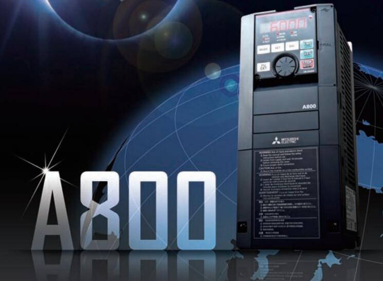
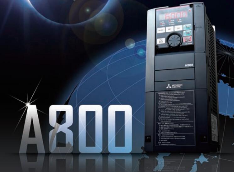
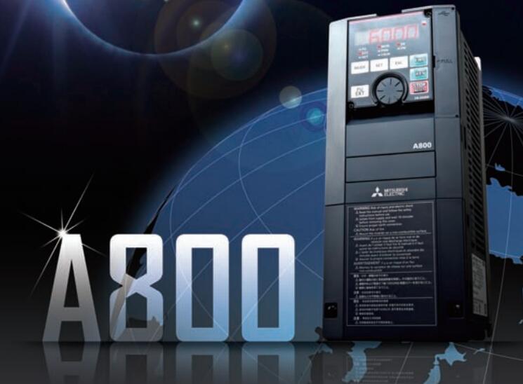
MITSUBISHI FR-A846-03250-2-60 Price
- Brand: MITSUBISHI
- Country: JAPAN
- Name: IP55 converter built-in DC reactor
- Model: FR-A846-03250-2-60
- Price: 0 >
MITSUBISHI FR-A846-03250-2-60
Output points: 32 points
Output form: Transistor (source).
Connection status: connector.
In order to extend the input output of the device.
Also has a built-in power supply products.
The maximum number of points for the input and output is 256.
Expansion module: up to 16 units (in addition to the power expansion module)
The total number of CC-Link, AnyWireASLINK, and Bitty series of remote I/O is 512 points FR-A846-03250-2-60 Max input / output points: 10 points.
Supply voltage: 100 - 240VAC.
Input points: 6 points.
Output points: 4 points.
Output type: Transistor (source).
Power consumption (W): 6.
Weight (kg):0.22.
Size (WxHxD) mm:60x90x49.
Host has 10 points (6I/4O), 14 points (8I/6O), 20 points (12I/8O), 30 points (16I/14O) of 4 types.
This type of PLC is mainly used in all of the digital input, digital output control point of the device.
Can be directly connected to the 220V city power, built-in 8K step EEPROM memory, no battery, easy to maintain.
The series transistor output (MT) of the PLC, can be output 2 100KHz pulse, direct drive servo or stepper motor.
The series PLC can not be brought with the expansion module, but can be installed by the BD board to extend a small amount of I/O.
The series 1N through the installation of BD series PLC board, can achieve RS232, RS485, RS422 communication. JEMANET (OPCN-1) interface unit master station.
The response time of PLC is the interval between the time of the change of the external output signal of the PLC and the time of the change of the external output signal which is controlled by it,
Lag time, this is the time constant of the input circuit,
The time constant of the output circuit, the arrangement of the user statement and the use of the instruction,
The cycle scan mode of PLC and the way of PLC to refresh the I/O and so on.
This phenomenon is called the I/O delay time effect.
Input status and input information input from the input interface,
CPU will be stored in the working data memory or in the input image register.
And then combine the data and the program with CPU.
The result is stored in the output image register or the working data memory,
And then output to the output interface, control the external drive.
FR-A846-03250-2-60 Operation manual/Instructions/Model selection sample download link: /searchDownload.html?Search=FR-A846-03250-2-60&select=5
...more relevant model market price >>>>
Related products
MITSUBISHI
IP55 converter built-in DC reactor
FR-A846-00770-2-60

"MITSUBISHI inverter series: FR-A846.
Vo
MITSUBISHI
IP55 converter built-in DC reactor
FR-A846-01800-2-60

"MITSUBISHI inverter series: FR-A846.
Vo
MITSUBISHI
IP55 converter built-in DC reactor
FR-A846-02160-2-60

"MITSUBISHI inverter series: FR-A846.
Vo
MITSUBISHI
IP55 converter built-in DC reactor
FR-A846-00083-2-60

"MITSUBISHI inverter series: FR-A846.
Vo

