 LK Automation Limited
Information sort
MITSUBISHI
A1SJ71B62-S3 The time constant of the output circuit, the arrangement of the user statement and the use of the instruction, MITSUBISHI A1SJ71B62-S3 Modular
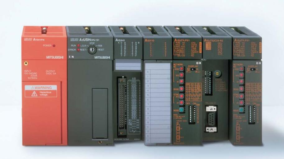
Output type: transistor source.
Output points: 16 points.
Load voltage: DC12/24.
Load current: 0.8A.
Connection mode: terminal row.
Common public end points: 8.
Switching value, also known as logic, refers to only two values, 0 or 1, ON or OFF.
It is the most common control, it is the advantage of PLC control,
Is also the most basic application of PLC A1SJ71B62-S33.
Switch volume control is designed to,
According to the current input combination of the switch quantity and the history of the input sequence,
So that PLC generates the corresponding switching output,
In order to make the system work in a certain order A1SJ71B62-S3.
So, sometimes also known as the order control.
And sequential control is divided into manual, semi-automatic or automatic.
And the control principle is decentralized, centralized and hybrid control three A1SJ71B62-S3. PLC station distance: 500M.
Cable type: coaxial cable.
The function of the MELSECNET interface module is to connect the main CPU PLC to the MELSECNET data communication system.
As long as the switch on the component to set,
Can determine the CPU PLC is as the main station or in situ station MITSUBISHI A1SJ71B62-S3.
There are two modules available for selection: one is the connection of the optical cable network and the network of the coaxial cable.
For a ANSCPU, up to only a piece of interface components can be inserted, A2ASCPU can be inserted 2 MITSUBISHI A1SJ71B62-S3.
The popularization and application of PLC programming has been developed rapidly in our country,
It has been widely used in all kinds of mechanical equipment and production process of electrical control devices,
All walks of life have emerged a large number of application of PLC transformation of the results of the equipment MITSUBISHI A1SJ71B62-S3.
Understand the working principle of PLC, have the ability to design, debug and maintain the PLC control system,
Has become the basic requirements of modern industry for electrical technicians and engineering students.
The instruction list programming language is a programming language similar to assembly language mnemonic,
As well as assembly language by the operation code and the number of operations.
In the case of the computer for the PLC handheld programmer compile user program.
At the same time, the programming language of the instruction list corresponds to the ladder diagram programming language,
In PLC programming software can be converted to each other. Figure 3 is the instruction sheet corresponding to the ladder diagram of figure 2PLC.
The characteristics of instruction table programming language is used to represent mnemonic operation function,
Easy to remember, easy to grasp;
In the handheld programmer on the keyboard using the mnemonic representation, easy to operate, can be programmed in computer;
There is a one-to-one correspondence between the ladder diagram and the ladder diagram. Its characteristics are basically consistent with the ladder diagram language.
Signal transmission device B/NET interface device for power distribution control equipment
The response time of PLC is the interval between the time of the change of the external output signal of the PLC and the time of the change of the external output signal which is controlled by it,
Lag time, this is the time constant of the input circuit,
The time constant of the output circuit, the arrangement of the user statement and the use of the instruction,
The cycle scan mode of PLC and the way of PLC to refresh the I/O and so on.
This phenomenon is called the I/O delay time effect.
Input status and input information input from the input interface,
CPU will be stored in the working data meemory or in the input image register A1SJ71B62-S3.
And then combine the data and the program with CPU.
The result is stored in the output image register or the working data memory,
And then output to the output interface, control the external drive.
Related supply information